Cirkit Designer Logo
Cirkit Designer
Your all-in-one circuit design IDE
Home / 
Component Documentation

How to Use Tether Interface Board DC 12V: Examples, Pinouts, and Specs

Image of Tether Interface Board DC 12V
Cirkit Designer LogoDesign with Tether Interface Board DC 12V in Cirkit Designer

Introduction

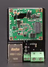
The Tether Interface Board DC 12V is a specialized circuit board designed to enable seamless communication and power delivery between a tethered device and its power source. Operating at a DC voltage of 12V, this board is ideal for applications requiring reliable power transmission and data exchange over a tethered connection. It is commonly used in robotics, underwater drones, industrial automation, and other systems where tethered communication is essential.

Explore Projects Built with Tether Interface Board DC 12V

Use Cirkit Designer to design, explore, and prototype these projects online. Some projects support real-time simulation. Click "Open Project" to start designing instantly!
Cellular-Enabled IoT Device with Real-Time Clock and Power Management
Image of LRCM PHASE 2 BASIC: A project utilizing Tether Interface Board DC 12V in a practical application
This circuit features a LilyGo-SIM7000G module for cellular communication and GPS functionality, interfaced with an RTC DS3231 for real-time clock capabilities. It includes voltage sensing through two voltage sensor modules, and uses an 8-channel opto-coupler for isolating different parts of the circuit. Power management is handled by a buck converter connected to a DC power source and batteries, with a fuse for protection and a rocker switch for on/off control. Additionally, there's an LED for indication purposes.
Cirkit Designer LogoOpen Project in Cirkit Designer
Satellite-Based Timing and Navigation System with SDR and Atomic Clock Synchronization
Image of GPS 시스템 측정 구성도_Confirm: A project utilizing Tether Interface Board DC 12V in a practical application
This circuit appears to be a complex system involving power supply management, GPS and timing synchronization, and data communication. It includes a SI-TEX G1 Satellite Compass for GPS data, an XHTF1021 Atomic Rubidium Clock for precise timing, and Ettus USRP B200 units for software-defined radio communication. Power is supplied through various SMPS units and distributed via terminal blocks and DC jacks. Data communication is facilitated by Beelink MINI S12 N95 computers, RS232 splitters, and a 1000BASE-T Media Converter for network connectivity. RF Directional Couplers are used to interface antennas with the USRP units, and the entire system is likely contained within cases for protection and organization.
Cirkit Designer LogoOpen Project in Cirkit Designer
Multi-Stage Voltage Regulation and Indicator LED Circuit
Image of Subramanyak_Power_Circuit: A project utilizing Tether Interface Board DC 12V in a practical application
This circuit is designed for power management, featuring buck and boost converters for voltage adjustment, and linear regulators for stable voltage output. It includes LEDs for status indication, and terminal blocks for external connections.
Cirkit Designer LogoOpen Project in Cirkit Designer
Solar-Powered GSM/GPRS+GPS Tracker with Seeeduino XIAO
Image of SOS System : A project utilizing Tether Interface Board DC 12V in a practical application
This circuit features an Ai Thinker A9G development board for GSM/GPRS and GPS/BDS connectivity, interfaced with a Seeeduino XIAO microcontroller for control and data processing. A solar cell, coupled with a TP4056 charging module, charges a 3.3V battery, which powers the system through a 3.3V regulator ensuring stable operation. The circuit likely serves for remote data communication and location tracking, with the capability to be powered by renewable energy and interfaced with additional sensors or input devices via the Seeeduino XIAO.
Cirkit Designer LogoOpen Project in Cirkit Designer

Explore Projects Built with Tether Interface Board DC 12V

Use Cirkit Designer to design, explore, and prototype these projects online. Some projects support real-time simulation. Click "Open Project" to start designing instantly!
Image of LRCM PHASE 2 BASIC: A project utilizing Tether Interface Board DC 12V in a practical application
Cellular-Enabled IoT Device with Real-Time Clock and Power Management
This circuit features a LilyGo-SIM7000G module for cellular communication and GPS functionality, interfaced with an RTC DS3231 for real-time clock capabilities. It includes voltage sensing through two voltage sensor modules, and uses an 8-channel opto-coupler for isolating different parts of the circuit. Power management is handled by a buck converter connected to a DC power source and batteries, with a fuse for protection and a rocker switch for on/off control. Additionally, there's an LED for indication purposes.
Cirkit Designer LogoOpen Project in Cirkit Designer
Image of GPS 시스템 측정 구성도_Confirm: A project utilizing Tether Interface Board DC 12V in a practical application
Satellite-Based Timing and Navigation System with SDR and Atomic Clock Synchronization
This circuit appears to be a complex system involving power supply management, GPS and timing synchronization, and data communication. It includes a SI-TEX G1 Satellite Compass for GPS data, an XHTF1021 Atomic Rubidium Clock for precise timing, and Ettus USRP B200 units for software-defined radio communication. Power is supplied through various SMPS units and distributed via terminal blocks and DC jacks. Data communication is facilitated by Beelink MINI S12 N95 computers, RS232 splitters, and a 1000BASE-T Media Converter for network connectivity. RF Directional Couplers are used to interface antennas with the USRP units, and the entire system is likely contained within cases for protection and organization.
Cirkit Designer LogoOpen Project in Cirkit Designer
Image of Subramanyak_Power_Circuit: A project utilizing Tether Interface Board DC 12V in a practical application
Multi-Stage Voltage Regulation and Indicator LED Circuit
This circuit is designed for power management, featuring buck and boost converters for voltage adjustment, and linear regulators for stable voltage output. It includes LEDs for status indication, and terminal blocks for external connections.
Cirkit Designer LogoOpen Project in Cirkit Designer
Image of SOS System : A project utilizing Tether Interface Board DC 12V in a practical application
Solar-Powered GSM/GPRS+GPS Tracker with Seeeduino XIAO
This circuit features an Ai Thinker A9G development board for GSM/GPRS and GPS/BDS connectivity, interfaced with a Seeeduino XIAO microcontroller for control and data processing. A solar cell, coupled with a TP4056 charging module, charges a 3.3V battery, which powers the system through a 3.3V regulator ensuring stable operation. The circuit likely serves for remote data communication and location tracking, with the capability to be powered by renewable energy and interfaced with additional sensors or input devices via the Seeeduino XIAO.
Cirkit Designer LogoOpen Project in Cirkit Designer

Common Applications and Use Cases

  • Powering and controlling underwater remotely operated vehicles (ROVs)
  • Enabling communication in tethered robotic systems
  • Industrial equipment requiring tethered power and data transfer
  • Surveillance systems with tethered cameras or sensors

Technical Specifications

The Tether Interface Board DC 12V is designed to operate efficiently in demanding environments. Below are its key technical details:

Electrical Specifications

Parameter Value
Operating Voltage 12V DC
Maximum Current 5A
Communication Protocol UART, RS-485, or CAN Bus
Power Efficiency >90%
Operating Temperature -20°C to 70°C
PCB Dimensions 100mm x 50mm x 20mm

Pin Configuration and Descriptions

The board features a set of input and output pins for power and communication. Below is the pinout:

Power and Communication Pins

Pin Number Name Description
1 VIN 12V DC power input
2 GND Ground connection
3 TX UART Transmit (data out)
4 RX UART Receive (data in)
5 CAN_H CAN Bus High
6 CAN_L CAN Bus Low
7 RS485_A RS-485 Differential Signal A
8 RS485_B RS-485 Differential Signal B
9 AUX_PWR_OUT Auxiliary power output (regulated 5V, 1A max)
10 SHIELD Shield connection for cable grounding

Usage Instructions

How to Use the Component in a Circuit

  1. Power Connection: Connect a 12V DC power source to the VIN pin and the ground to the GND pin.
  2. Communication Setup: Depending on your application, connect the appropriate communication pins:
    • For UART communication, use the TX and RX pins.
    • For CAN Bus, connect CAN_H and CAN_L.
    • For RS-485, connect RS485_A and RS485_B.
  3. Auxiliary Power: If your tethered device requires a 5V power supply, use the AUX_PWR_OUT pin.
  4. Shielding: Connect the SHIELD pin to the cable shield to reduce electromagnetic interference.

Important Considerations and Best Practices

  • Ensure the power source provides a stable 12V DC output to avoid damaging the board.
  • Use proper shielding for the tether cable to minimize noise and signal degradation.
  • Verify the communication protocol (UART, RS-485, or CAN Bus) matches the requirements of your tethered device.
  • Avoid exceeding the maximum current rating of 5A to prevent overheating or damage.

Example: Connecting to an Arduino UNO

The Tether Interface Board can be easily interfaced with an Arduino UNO for UART communication. Below is an example code snippet:

// Example: Communicating with the Tether Interface Board via UART
// Connect TX (Pin 3) of the board to RX (Pin 0) of Arduino UNO
// Connect RX (Pin 4) of the board to TX (Pin 1) of Arduino UNO
// Ensure GND of the board is connected to GND of Arduino UNO

void setup() {
  Serial.begin(9600); // Initialize UART communication at 9600 baud rate
  Serial.println("Tether Interface Board Communication Initialized");
}

void loop() {
  // Send a test message to the Tether Interface Board
  Serial.println("Hello, Tether Interface Board!");

  // Check if data is available from the board
  if (Serial.available() > 0) {
    String receivedData = Serial.readString(); // Read incoming data
    Serial.print("Received: ");
    Serial.println(receivedData); // Print received data to Serial Monitor
  }

  delay(1000); // Wait for 1 second before sending the next message
}

Troubleshooting and FAQs

Common Issues and Solutions

  1. No Power to the Board

    • Cause: Incorrect or unstable power supply.
    • Solution: Verify the power source provides a stable 12V DC output and check the connections to VIN and GND.
  2. Communication Failure

    • Cause: Incorrect wiring or mismatched communication protocol.
    • Solution: Double-check the connections for TX, RX, CAN_H, CAN_L, RS485_A, and RS485_B. Ensure the protocol settings (e.g., baud rate) match between the board and the connected device.
  3. Overheating

    • Cause: Exceeding the maximum current rating of 5A.
    • Solution: Reduce the load on the board and ensure proper ventilation.
  4. Signal Noise or Interference

    • Cause: Poor shielding or long tether cables.
    • Solution: Use a shielded cable and connect the SHIELD pin to the cable shield.

FAQs

  • Q: Can I use a power source other than 12V DC?
    A: No, the board is designed to operate specifically at 12V DC. Using a different voltage may damage the board.

  • Q: What is the maximum tether length supported?
    A: The maximum tether length depends on the communication protocol and cable quality. For UART, shorter lengths are recommended, while RS-485 and CAN Bus can support longer distances (up to 1000 meters with proper shielding).

  • Q: Can I use the board outdoors?
    A: The board is not weatherproof. If outdoor use is required, ensure it is enclosed in a waterproof and dustproof housing.

This concludes the documentation for the Tether Interface Board DC 12V. For further assistance, refer to the manufacturer's support resources.