
How to Use NRF24LE1: Examples, Pinouts, and Specs
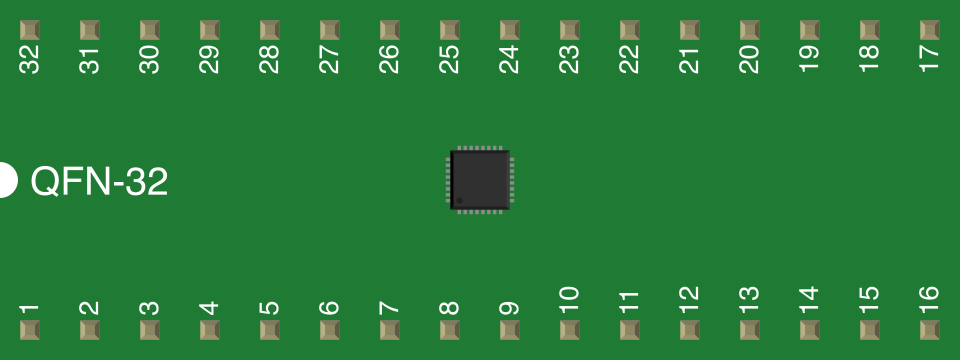
 Design with NRF24LE1 in Cirkit Designer
Introduction
The NRF24LE1 is a low-power, 2.4 GHz transceiver with an integrated microcontroller, designed for wireless communication in embedded systems. It combines a high-performance RF transceiver with an 8-bit microcontroller, making it ideal for compact and efficient wireless solutions. The device supports multiple data rates (250 kbps, 1 Mbps, and 2 Mbps) and features a built-in Enhanced ShockBurst™ protocol for reliable and efficient data transmission.
Explore Projects Built with NRF24LE1
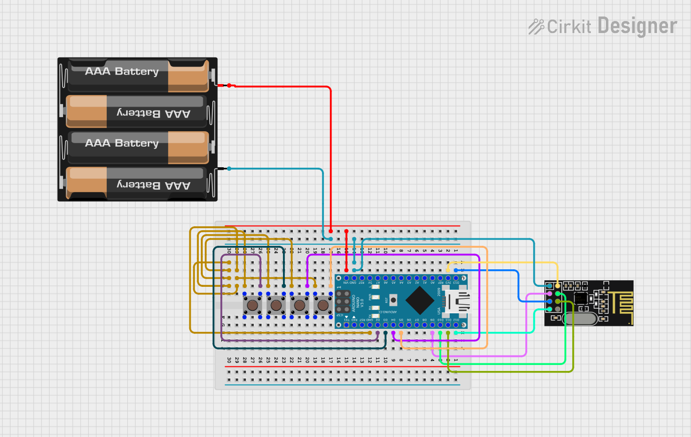 Open Project in Cirkit Designer
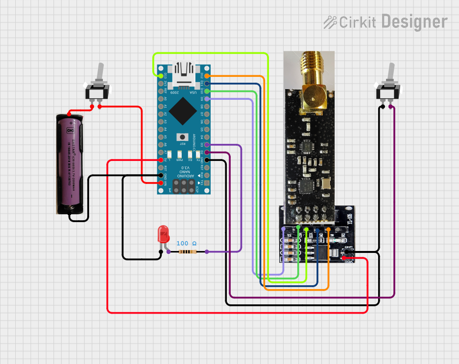 Open Project in Cirkit Designer
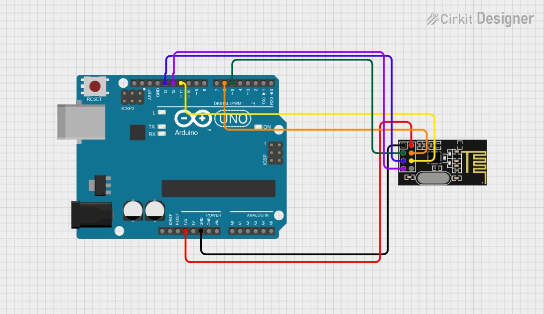 Open Project in Cirkit Designer
 Open Project in Cirkit Designer
Explore Projects Built with NRF24LE1
Open Project in Cirkit DesignerOpen Project in Cirkit DesignerOpen Project in Cirkit DesignerOpen Project in Cirkit DesignerCommon Applications and Use Cases
- Wireless sensor networks
- Remote controls and home automation
- Industrial monitoring and control systems
- Wireless gaming peripherals
- Consumer electronics requiring low-power wireless communication
Technical Specifications
The NRF24LE1 offers a robust set of features for wireless communication. Below are its key technical details:
Key Technical Details
| Parameter | Value |
|---|---|
| Frequency Range | 2.4 GHz ISM band |
| Data Rates | 250 kbps, 1 Mbps, 2 Mbps |
| Operating Voltage | 1.9 V to 3.6 V |
| Current Consumption | 13 mA (RX mode), 11 mA (TX mode @ 0 dBm) |
| Sleep Mode Current | 0.9 µA |
| Microcontroller Core | 8-bit 8051 compatible |
| Flash Memory | 16/32/64 kB (depending on variant) |
| RAM | 1 kB |
| GPIO Pins | Up to 18 |
| Communication Interfaces | SPI, UART, I2C |
| Operating Temperature | -40°C to +85°C |
Pin Configuration and Descriptions
The NRF24LE1 is available in multiple package types (e.g., QFN32). Below is the pin configuration for the QFN32 package:
| Pin Number | Pin Name | Description |
|---|---|---|
| 1 | VDD | Power supply (1.9 V to 3.6 V) |
| 2 | GND | Ground |
| 3 | P0.0 | GPIO/ADC input |
| 4 | P0.1 | GPIO/ADC input |
| 5 | P0.2 | GPIO/ADC input |
| 6 | P0.3 | GPIO/ADC input |
| 7 | P0.4 | GPIO/ADC input |
| 8 | P0.5 | GPIO/ADC input |
| 9 | P0.6 | GPIO/ADC input |
| 10 | P0.7 | GPIO/ADC input |
| 11 | P1.0 | GPIO/Interrupt |
| 12 | P1.1 | GPIO/Interrupt |
| 13 | P1.2 | GPIO/Interrupt |
| 14 | P1.3 | GPIO/Interrupt |
| 15 | P1.4 | GPIO/Interrupt |
| 16 | P1.5 | GPIO/Interrupt |
| 17 | P1.6 | GPIO/Interrupt |
| 18 | P1.7 | GPIO/Interrupt |
| 19 | SPI_MOSI | SPI Master Out Slave In |
| 20 | SPI_MISO | SPI Master In Slave Out |
| 21 | SPI_SCK | SPI Clock |
| 22 | SPI_CSN | SPI Chip Select |
| 23 | UART_TX | UART Transmit |
| 24 | UART_RX | UART Receive |
| 25 | RESET | Reset Pin |
| 26 | XTAL1 | Crystal Oscillator Input |
| 27 | XTAL2 | Crystal Oscillator Output |
| 28 | ANT1 | RF Antenna Connection |
| 29 | ANT2 | RF Antenna Connection |
| 30 | VDD_PA | Power Amplifier Supply |
| 31 | GND_PA | Power Amplifier Ground |
| 32 | TEST | Test Pin (for factory use) |
Usage Instructions
The NRF24LE1 is versatile and can be used in various wireless applications. Below are the steps and considerations for using it in a circuit:
How to Use the NRF24LE1 in a Circuit
- Power Supply: Connect the VDD pin to a stable power source (1.9 V to 3.6 V) and GND to ground.
- Antenna Connection: Attach a suitable 2.4 GHz antenna to the ANT1 and ANT2 pins for optimal RF performance.
- Crystal Oscillator: Connect a 16 MHz crystal oscillator to the XTAL1 and XTAL2 pins for clock generation.
- SPI Communication: Use the SPI interface (MOSI, MISO, SCK, CSN) to communicate with the NRF24LE1 from an external microcontroller if needed.
- GPIO Configuration: Configure the GPIO pins as inputs or outputs based on your application requirements.
- Programming: Use the built-in 8051 microcontroller to write and execute custom firmware for your application.
Important Considerations and Best Practices
- Decoupling Capacitors: Place decoupling capacitors (e.g., 0.1 µF) close to the VDD pin to reduce noise.
- PCB Design: Ensure proper RF layout and grounding to minimize interference and maximize performance.
- Firmware Development: Use Nordic Semiconductor's development tools and SDKs for efficient firmware development.
- Power Management: Utilize the sleep mode to reduce power consumption in battery-powered applications.
Example Code for Arduino UNO
Although the NRF24LE1 has an integrated microcontroller, it can also be interfaced with an Arduino UNO for certain applications. Below is an example of initializing communication with the NRF24LE1 using SPI:
#include <SPI.h>

// Define NRF24LE1 SPI pins
#define CSN_PIN 10  // Chip Select Not pin
#define SCK_PIN 13  // Serial Clock pin
#define MOSI_PIN 11 // Master Out Slave In pin
#define MISO_PIN 12 // Master In Slave Out pin

void setup() {
  // Initialize SPI communication
  SPI.begin();

  // Configure CSN pin as output
  pinMode(CSN_PIN, OUTPUT);
  digitalWrite(CSN_PIN, HIGH); // Set CSN high to deselect the NRF24LE1

  // Configure SPI settings
  SPI.beginTransaction(SPISettings(8000000, MSBFIRST, SPI_MODE0));

  Serial.begin(9600); // Initialize serial communication for debugging
  Serial.println("NRF24LE1 Initialized");
}

void loop() {
  // Example: Send a command to the NRF24LE1
  digitalWrite(CSN_PIN, LOW); // Select the NRF24LE1
  SPI.transfer(0x00);         // Send a dummy command (replace with actual command)
  digitalWrite(CSN_PIN, HIGH); // Deselect the NRF24LE1

  delay(1000); // Wait for 1 second
}
Troubleshooting and FAQs
Common Issues and Solutions
No Communication with NRF24LE1
- Solution: Verify SPI connections and ensure the correct SPI settings (clock speed, mode).
- Tip: Check the CSN pin state during communication (should be LOW).
Poor RF Performance
- Solution: Ensure proper antenna placement and PCB layout.
- Tip: Use a ground plane and avoid placing components near the antenna.
High Power Consumption
- Solution: Enable sleep mode when the device is idle.
- Tip: Use power management features in your firmware.
Firmware Upload Issues
- Solution: Verify the programming interface and ensure the correct firmware is being used.
- Tip: Use Nordic's development tools for debugging.
FAQs
Q: Can the NRF24LE1 operate without an external microcontroller?
A: Yes, the NRF24LE1 has a built-in 8051 microcontroller for standalone operation.Q: What is the maximum range of the NRF24LE1?
A: The range depends on the antenna and environment but typically reaches up to 100 meters in open space.Q: Can I use the NRF24LE1 with a 5V system?
A: No, the NRF24LE1 operates at 1.9 V to 3.6 V. Use a level shifter for 5V systems.