How to Use LM311: Examples, Pinouts, and Specs
Introduction
The LM311, manufactured by Vedant, is a versatile voltage comparator designed for high-speed and precision voltage comparison tasks. It operates over a wide range of voltages and can drive loads up to 50V and 50mA. This makes it suitable for a variety of applications, including:
- Zero-crossing detectors
- Voltage level shifters
- Oscillators
- Peak detectors
- Analog-to-digital converters
Explore Projects Built with LM311

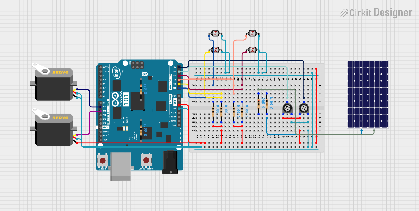
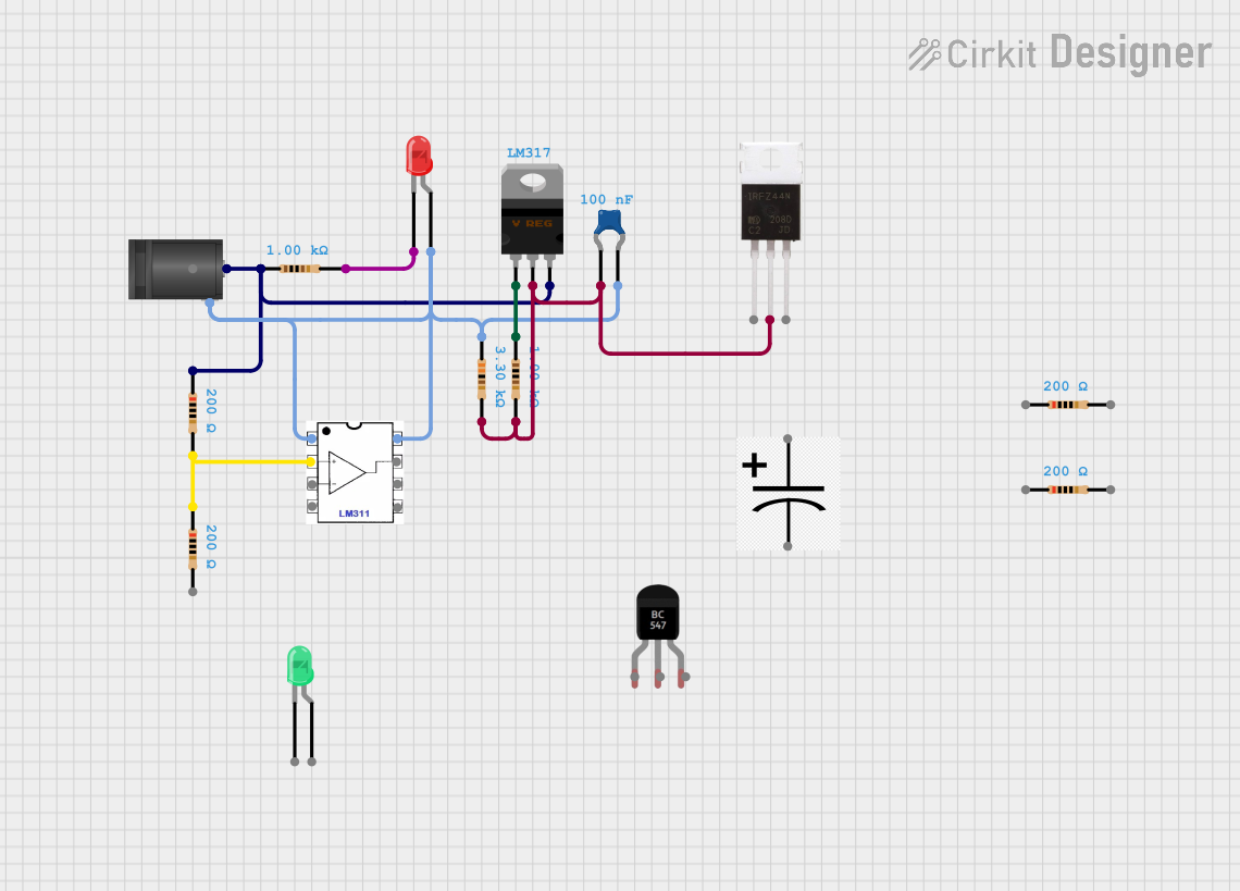
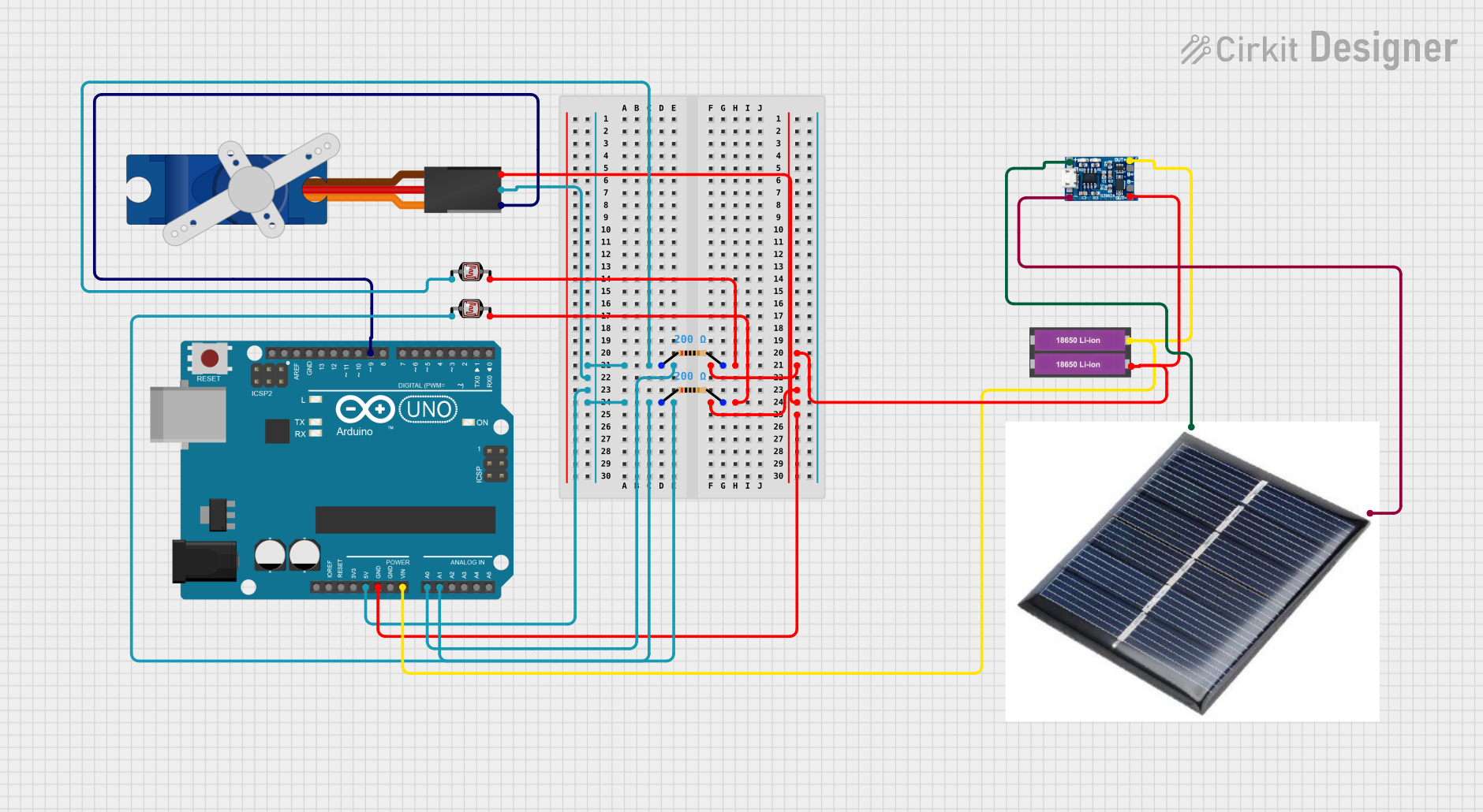
Explore Projects Built with LM311
Technical Specifications
Key Technical Details
| Parameter | Value |
|---|---|
| Supply Voltage Range | ±3V to ±18V |
| Input Offset Voltage | 7.5mV (max) |
| Input Bias Current | 250nA (typ) |
| Input Voltage Range | -0.5V to +30V |
| Output Current | 50mA (max) |
| Response Time | 200ns (typ) |
| Operating Temperature | 0°C to +70°C |
| Package | 8-Pin DIP, SOIC |
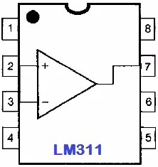
Pin Configuration and Descriptions
| Pin No. | Pin Name | Description |
|---|---|---|
| 1 | Offset Null | Offset nulling input |
| 2 | Inverting Input | Inverting input of the comparator |
| 3 | Non-Inverting Input | Non-inverting input of the comparator |
| 4 | V- (Ground) | Negative power supply (Ground) |
| 5 | Offset Null | Offset nulling input |
| 6 | Output | Output of the comparator |
| 7 | V+ (Supply) | Positive power supply |
| 8 | Strobe | Strobe input (used to disable the output) |
Usage Instructions
How to Use the LM311 in a Circuit
- Power Supply: Connect the V+ pin (Pin 7) to the positive supply voltage and the V- pin (Pin 4) to the ground.
- Input Connections: Connect the voltage to be compared to the inverting (Pin 2) and non-inverting (Pin 3) inputs.
- Output Connection: The output (Pin 6) can be connected to a load or another stage in your circuit.
- Offset Nulling: If precise offset nulling is required, connect a potentiometer between the offset null pins (Pins 1 and 5) and adjust accordingly.
- Strobe Function: If you need to disable the output, apply a high signal to the strobe pin (Pin 8).
Important Considerations and Best Practices
- Decoupling Capacitors: Place decoupling capacitors (0.1µF) close to the power supply pins to filter out noise.
- Input Protection: Use resistors or diodes to protect the inputs from voltage spikes.
- Output Load: Ensure the load connected to the output does not exceed the maximum current rating of 50mA.
- Thermal Management: Ensure adequate cooling if the device is operating near its maximum ratings.
Example Circuit with Arduino UNO
Here is an example of how to use the LM311 with an Arduino UNO to create a simple voltage comparator circuit:
// Define the pin connected to the LM311 output
const int comparatorOutputPin = 2;

void setup() {
  // Initialize the serial communication
  Serial.begin(9600);

  // Set the comparator output pin as input
  pinMode(comparatorOutputPin, INPUT);
}

void loop() {
  // Read the comparator output
  int comparatorState = digitalRead(comparatorOutputPin);

  // Print the comparator state to the serial monitor
  Serial.print("Comparator State: ");
  Serial.println(comparatorState);

  // Add a small delay to avoid flooding the serial monitor
  delay(500);
}
Troubleshooting and FAQs
Common Issues and Solutions
No Output Signal:
- Check Power Supply: Ensure the V+ and V- pins are connected to the correct supply voltages.
- Verify Connections: Double-check all input and output connections.
- Strobe Pin: Ensure the strobe pin is not disabling the output.
Incorrect Output:
- Input Voltage Range: Ensure the input voltages are within the specified range.
- Offset Adjustment: Adjust the offset null potentiometer if necessary.
Noise and Instability:
- Decoupling Capacitors: Add or check decoupling capacitors on the power supply pins.
- Shielding: Use proper shielding and grounding techniques to minimize noise.
FAQs
Q1: Can the LM311 be used for high-frequency applications? A1: Yes, the LM311 has a typical response time of 200ns, making it suitable for high-speed applications.
Q2: What is the purpose of the strobe pin? A2: The strobe pin is used to disable the output. When a high signal is applied to the strobe pin, the output is disabled.
Q3: How do I adjust the offset voltage? A3: Connect a potentiometer between the offset null pins (Pins 1 and 5) and adjust it to minimize the offset voltage.
Q4: Can the LM311 drive a relay directly? A4: Yes, the LM311 can drive loads up to 50V and 50mA, which is sufficient for many small relays.
By following this documentation, users can effectively utilize the LM311 voltage comparator in their electronic projects, ensuring high-speed and precise voltage comparison.