
How to Use USB Connectors: Examples, Pinouts, and Specs
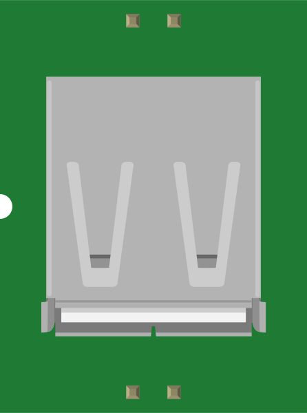
 Design with USB Connectors in Cirkit Designer
Introduction
USB connectors, such as the SparkFun USB-A-S-NOSILK, are standardized interfaces widely used for connecting electronic devices to computers, power sources, and other peripherals. These connectors facilitate data transfer, device communication, and power delivery. The USB-A-S-NOSILK is a robust and reliable USB Type-A connector designed for through-hole PCB mounting, making it ideal for a variety of DIY electronics projects and professional applications.
Explore Projects Built with USB Connectors
 Open Project in Cirkit Designer
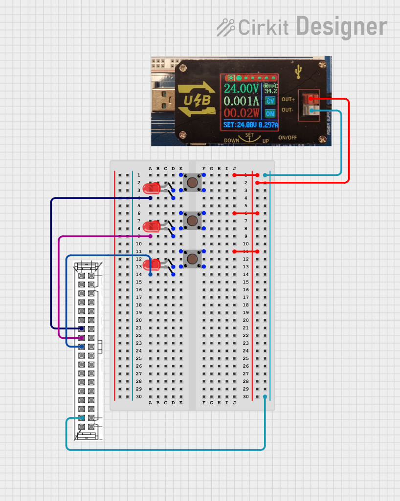 Open Project in Cirkit Designer
 Open Project in Cirkit Designer
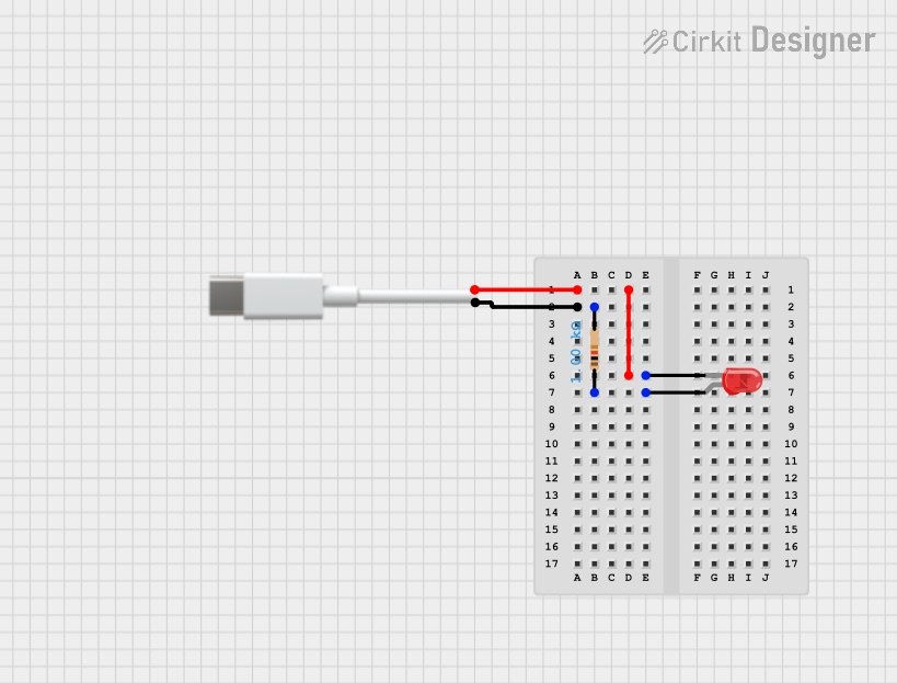 Open Project in Cirkit Designer
Explore Projects Built with USB Connectors
Open Project in Cirkit DesignerOpen Project in Cirkit DesignerOpen Project in Cirkit DesignerOpen Project in Cirkit DesignerCommon Applications and Use Cases
- Connecting microcontrollers (e.g., Arduino, Raspberry Pi) to computers for programming and data transfer
- Powering devices via USB power sources
- Building custom USB hubs or chargers
- Prototyping and repairing USB-enabled devices
Technical Specifications
The SparkFun USB-A-S-NOSILK connector is designed to meet the USB 2.0 standard, ensuring compatibility with a wide range of devices. Below are the key technical details:
General Specifications
| Parameter | Value |
|---|---|
| Manufacturer | SparkFun |
| Part ID | USB-A-S-NOSILK |
| USB Standard | USB 2.0 |
| Connector Type | USB Type-A (Female) |
| Mounting Style | Through-hole |
| Operating Voltage | 5V DC |
| Maximum Current Rating | 1.5A |
| Contact Material | Gold-plated contacts |
| Housing Material | Thermoplastic, UL94V-0 rated |
| Dimensions | 15.9mm x 14.5mm x 13.5mm |
Pin Configuration and Descriptions
The USB-A-S-NOSILK connector has four pins, as per the USB 2.0 standard. The pinout is as follows:
| Pin Number | Name | Description |
|---|---|---|
| 1 | VBUS | +5V power supply |
| 2 | D- | Data line (negative) |
| 3 | D+ | Data line (positive) |
| 4 | GND | Ground |
Usage Instructions
How to Use the USB-A-S-NOSILK in a Circuit
- PCB Mounting: The USB-A-S-NOSILK is a through-hole component. Ensure your PCB design includes appropriately sized holes for the connector's pins and mounting tabs.
- Soldering: Insert the connector into the PCB and solder the pins and mounting tabs securely. Use a soldering iron with a fine tip for precision.
- Connections:
- Connect the VBUS pin to a 5V power source.
- Connect the D- and D+ pins to the corresponding data lines of your microcontroller or USB device.
- Connect the GND pin to the ground plane of your circuit.
Important Considerations and Best Practices
- Power Handling: Ensure the connected device does not exceed the 1.5A current rating of the connector.
- Data Integrity: Use short, high-quality wires for the D- and D+ lines to minimize signal degradation.
- Mounting Stability: Secure the connector to the PCB using the mounting tabs to prevent mechanical stress on the solder joints.
- USB Compliance: Follow USB 2.0 specifications for proper operation and compatibility.
Example: Connecting to an Arduino UNO
The USB-A-S-NOSILK can be used to create a custom USB cable for programming an Arduino UNO. Below is an example Arduino sketch for basic serial communication:
// Example: Serial Communication with Arduino UNO
// This code sends "Hello, USB!" to the serial monitor every second.

void setup() {
  Serial.begin(9600); // Initialize serial communication at 9600 baud
}

void loop() {
  Serial.println("Hello, USB!"); // Send message to the serial monitor
  delay(1000); // Wait for 1 second
}
Troubleshooting and FAQs
Common Issues
- Loose Connections: If the USB connector feels loose or wobbly, check the solder joints and ensure the mounting tabs are securely attached to the PCB.
- No Power or Data Transfer: Verify the pin connections, especially the VBUS and GND lines. Ensure the D- and D+ lines are correctly connected to the data pins of the USB device or microcontroller.
- Overheating: If the connector becomes hot, the connected device may be drawing more current than the 1.5A rating. Disconnect the device immediately and check its power requirements.
Solutions and Tips for Troubleshooting
- Use a multimeter to check continuity between the connector pins and the corresponding PCB traces.
- Inspect the solder joints for cold soldering or bridging between pins.
- Ensure the USB cable and connected devices are functioning properly by testing them with another USB port.
By following this documentation, you can effectively integrate the SparkFun USB-A-S-NOSILK connector into your projects, ensuring reliable performance and compliance with USB standards.