How to Use Rasberry Pi5: Examples, Pinouts, and Specs
Introduction
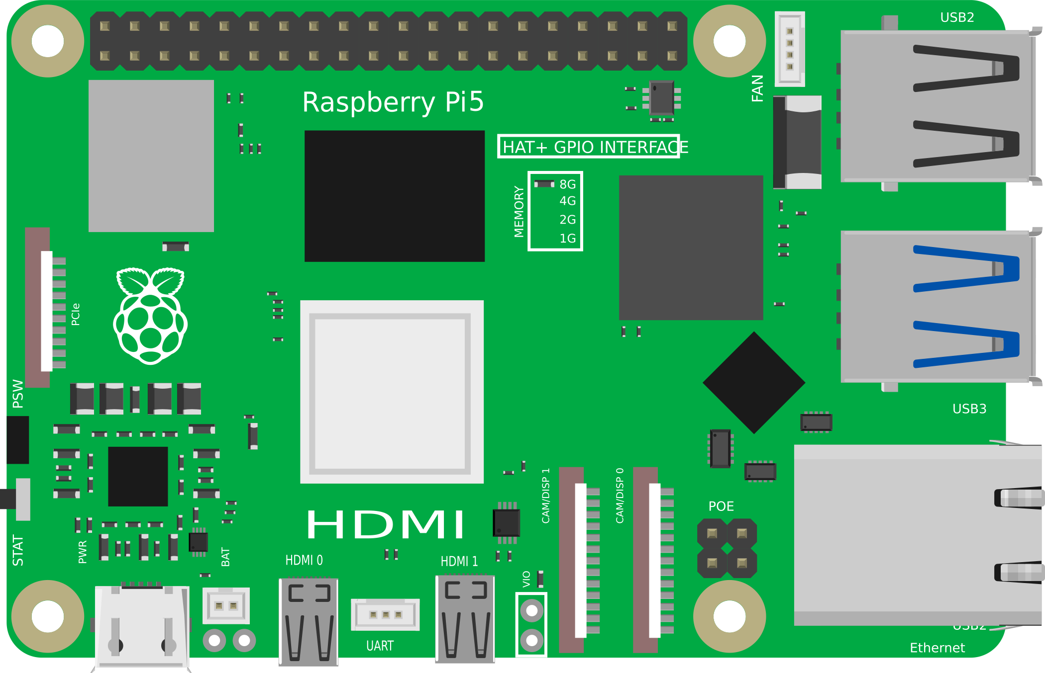
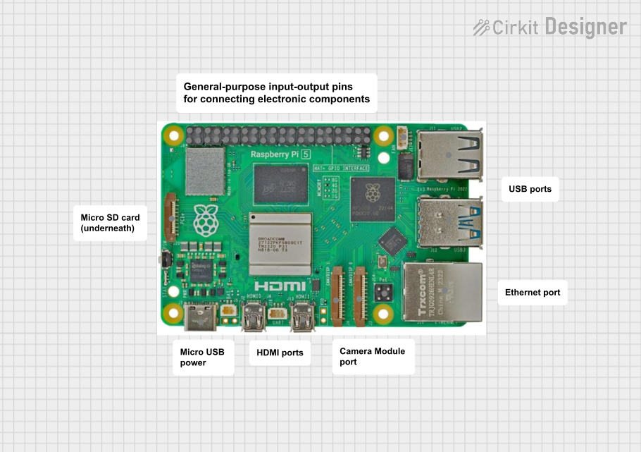
The Raspberry Pi 5, manufactured by Raspberry, is a compact and affordable single-board computer designed for a wide range of applications. It supports various programming languages and is ideal for projects in electronics, robotics, and the Internet of Things (IoT). With its enhanced processing power, improved connectivity, and versatile GPIO pins, the Raspberry Pi 5 is a powerful tool for hobbyists, educators, and professionals alike.
Explore Projects Built with Rasberry Pi5
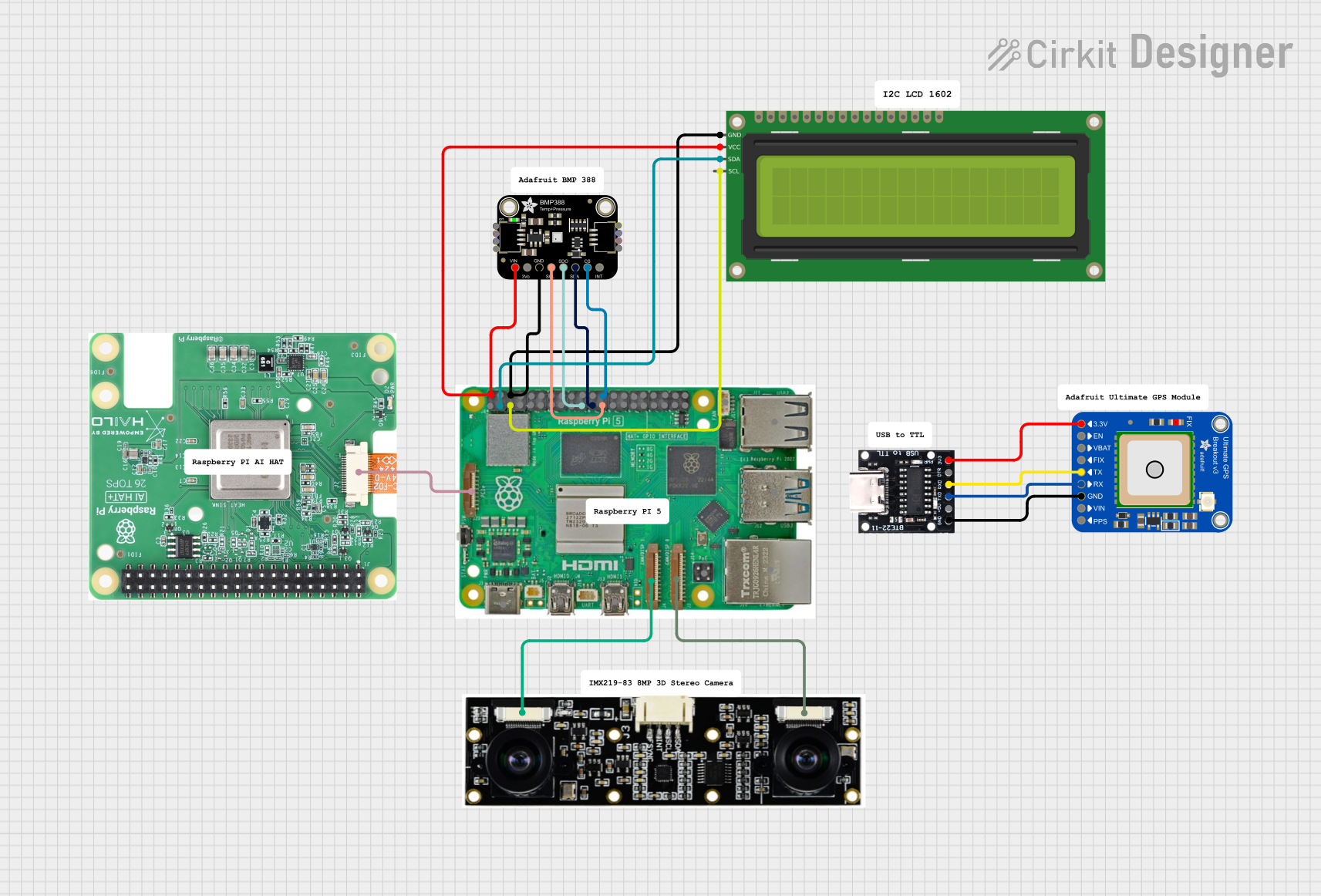
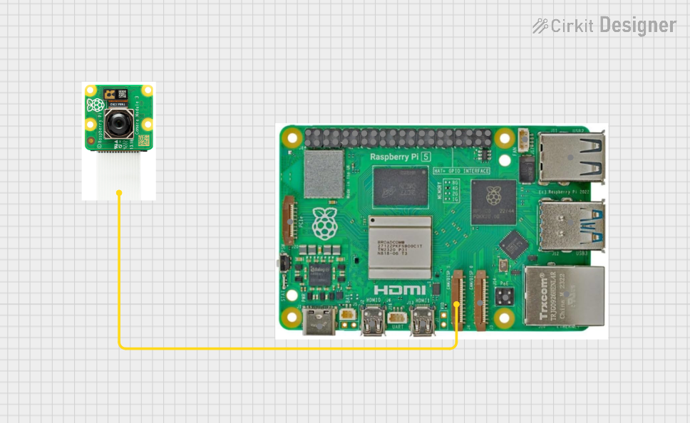
Explore Projects Built with Rasberry Pi5
Common Applications and Use Cases
- IoT Projects: Build smart home devices, sensors, and automation systems.
- Robotics: Control motors, servos, and sensors for robotics applications.
- Media Centers: Create a home theater system using software like Kodi.
- Programming Education: Learn and teach programming languages such as Python, C++, and Java.
- Prototyping: Develop and test hardware and software for embedded systems.
- Edge Computing: Deploy lightweight AI and machine learning models at the edge.
Technical Specifications
The Raspberry Pi 5 offers significant improvements over its predecessors, making it a versatile and powerful platform for various projects.
Key Technical Details
| Specification | Details |
|---|---|
| Processor | Quad-core ARM Cortex-A76, 2.4 GHz |
| GPU | VideoCore VII, supports 4K video playback |
| RAM | 4GB or 8GB LPDDR4X |
| Storage | MicroSD card slot, support for external SSD via USB 3.0 |
| Connectivity | Dual-band Wi-Fi 6, Bluetooth 5.2, Gigabit Ethernet |
| USB Ports | 2 × USB 3.0, 2 × USB 2.0 |
| GPIO Pins | 40-pin header, 3.3V logic level |
| Power Supply | USB-C, 5V/5A |
| Display Output | 2 × micro-HDMI ports, supports dual 4K displays |
| Audio Output | 3.5mm audio jack, HDMI audio |
| Dimensions | 85.6mm × 56.5mm × 17mm |
GPIO Pin Configuration
The Raspberry Pi 5 features a 40-pin GPIO header for interfacing with external components. Below is the pinout:
| Pin Number | Pin Name | Description |
|---|---|---|
| 1 | 3.3V Power | Power supply (3.3V) |
| 2 | 5V Power | Power supply (5V) |
| 3 | GPIO2 (SDA1) | I2C Data |
| 4 | 5V Power | Power supply (5V) |
| 5 | GPIO3 (SCL1) | I2C Clock |
| 6 | Ground | Ground |
| 7 | GPIO4 | General-purpose I/O |
| 8 | GPIO14 (TXD) | UART Transmit |
| 9 | Ground | Ground |
| 10 | GPIO15 (RXD) | UART Receive |
| ... | ... | ... |
| 39 | Ground | Ground |
| 40 | GPIO21 | General-purpose I/O |
For the full GPIO pinout, refer to the official Raspberry Pi documentation.
Usage Instructions
How to Use the Raspberry Pi 5 in a Circuit
Powering the Raspberry Pi 5:
- Use a USB-C power adapter capable of supplying 5V/5A.
- Ensure the power supply is stable to avoid performance issues.
Connecting Peripherals:
- Attach a monitor via the micro-HDMI ports.
- Connect a keyboard and mouse to the USB ports.
- Insert a microSD card with the Raspberry Pi OS or another compatible operating system.
Using GPIO Pins:
- Use jumper wires to connect the GPIO pins to external components like LEDs, sensors, or motors.
- Be cautious of voltage levels; the GPIO pins operate at 3.3V logic.
Networking:
- Connect to the internet via Wi-Fi 6 or Gigabit Ethernet for remote access and updates.
Important Considerations and Best Practices
- Static Protection: Handle the Raspberry Pi 5 with care to avoid static discharge, which can damage the board.
- Cooling: Use a heatsink or fan for cooling during intensive tasks to prevent overheating.
- Software Updates: Regularly update the operating system and firmware for optimal performance and security.
- GPIO Safety: Avoid short circuits and overvoltage on GPIO pins to prevent damage.
Example: Blinking an LED with Raspberry Pi 5
Below is an example Python script to blink an LED connected to GPIO pin 17:
Import the necessary library for GPIO control
import RPi.GPIO as GPIO import time
Set up GPIO mode and pin
GPIO.setmode(GPIO.BCM) # Use Broadcom pin numbering GPIO.setup(17, GPIO.OUT) # Set GPIO pin 17 as an output
try: while True: GPIO.output(17, GPIO.HIGH) # Turn on the LED time.sleep(1) # Wait for 1 second GPIO.output(17, GPIO.LOW) # Turn off the LED time.sleep(1) # Wait for 1 second except KeyboardInterrupt: # Clean up GPIO settings when the script is interrupted GPIO.cleanup()
**Note**: Ensure the LED is connected to GPIO pin 17 with a current-limiting resistor (e.g., 330Ω) to prevent damage.
Troubleshooting and FAQs
Common Issues and Solutions
The Raspberry Pi 5 does not boot:
- Ensure the microSD card is properly inserted and contains a valid operating system.
- Check the power supply for sufficient voltage and current.
Overheating:
- Use a heatsink or fan to improve cooling.
- Avoid running intensive tasks for extended periods without proper cooling.
No display output:
- Verify the micro-HDMI cable is securely connected.
- Ensure the monitor is set to the correct input source.
GPIO pins not working:
- Double-check the pin connections and ensure the correct pin numbering is used in the code.
- Confirm that the GPIO pins are not damaged or shorted.
FAQs
Can I use the Raspberry Pi 5 with an external SSD? Yes, the Raspberry Pi 5 supports external SSDs via USB 3.0 for faster storage access.
What operating systems are compatible with the Raspberry Pi 5? The Raspberry Pi 5 supports Raspberry Pi OS, Ubuntu, and other Linux-based distributions.
How do I reset the Raspberry Pi 5? Disconnect and reconnect the power supply to perform a hard reset.
Can I power the Raspberry Pi 5 via GPIO pins? Yes, you can power it via the 5V and GND pins, but ensure a stable 5V supply is used.
By following this documentation, users can effectively utilize the Raspberry Pi 5 for a variety of projects and applications.