Cirkit Designer
Your all-in-one circuit design IDE
Home /
Component Documentation
How to Use USB to serial converter: Examples, Pinouts, and Specs
Introduction
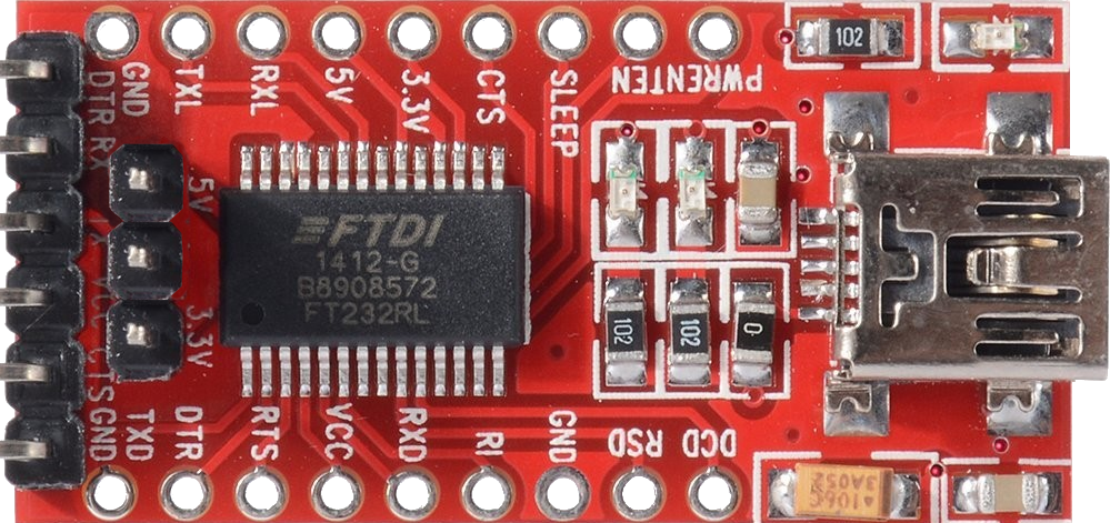
The USB to Serial Converter featuring the FT232RL chip by AZDelivery is a versatile and essential tool for connecting serial devices to a USB interface. This component is widely used in the development and debugging of microcontroller-based projects, interfacing with GPS modules, programming Arduino boards without USB support, and bridging communication between a computer and various networking equipment.
Explore Projects Built with USB to serial converter
FTDI to UART Adapter with J26 Connector

This circuit connects an FTDI USB-to-serial converter to a standard serial interface via a J26 connector. It facilitates serial communication by linking the ground, transmit, receive, data terminal ready, and request to send signals between the FTDI chip and the J26 connector.
Arduino UNO RS232 Serial Communication Interface
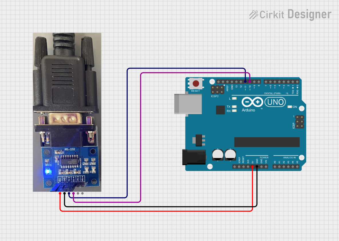
This circuit connects an Arduino UNO to an RS232 to Serial Converter, allowing the Arduino to communicate with RS232-compatible devices. The Arduino's digital pins D10 and D11 are used for RX and TX communication, respectively, and are interfaced with the corresponding TX and RX pins of the RS232 converter. The embedded code on the Arduino sets up a software serial port for communication with the RS232 converter and relays data between the standard serial port and the software serial port.
Dual Hub Motor Control System with USB to TTL Interface and Relay Switching

This circuit is designed to control two hub motors using a HUB driver, powered by a DC-DC converter and a power module. The USB to TTL converter allows for communication with the HUB driver, and a 5V relay module is used to switch the motors on and off.
Arduino UNO and MAX 3232 Module Controlled NE-1000 Pump System
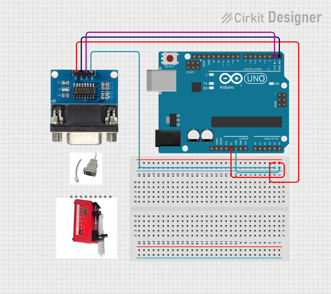
This circuit features an Arduino UNO microcontroller interfaced with a MAX 3232 module for serial communication. The Arduino provides power and ground to the MAX 3232, and the two devices communicate via the TxD and RxD pins. The setup is likely intended for serial data transmission between the Arduino and another device.
Explore Projects Built with USB to serial converter
FTDI to UART Adapter with J26 Connector
This circuit connects an FTDI USB-to-serial converter to a standard serial interface via a J26 connector. It facilitates serial communication by linking the ground, transmit, receive, data terminal ready, and request to send signals between the FTDI chip and the J26 connector.
Arduino UNO RS232 Serial Communication Interface
This circuit connects an Arduino UNO to an RS232 to Serial Converter, allowing the Arduino to communicate with RS232-compatible devices. The Arduino's digital pins D10 and D11 are used for RX and TX communication, respectively, and are interfaced with the corresponding TX and RX pins of the RS232 converter. The embedded code on the Arduino sets up a software serial port for communication with the RS232 converter and relays data between the standard serial port and the software serial port.
Dual Hub Motor Control System with USB to TTL Interface and Relay Switching
This circuit is designed to control two hub motors using a HUB driver, powered by a DC-DC converter and a power module. The USB to TTL converter allows for communication with the HUB driver, and a 5V relay module is used to switch the motors on and off.
Arduino UNO and MAX 3232 Module Controlled NE-1000 Pump System
This circuit features an Arduino UNO microcontroller interfaced with a MAX 3232 module for serial communication. The Arduino provides power and ground to the MAX 3232, and the two devices communicate via the TxD and RxD pins. The setup is likely intended for serial data transmission between the Arduino and another device.
Common Applications and Use Cases
- Microcontroller programming and debugging
- Serial communication with GPS modules, modems, and other peripherals
- Interface for industrial equipment
- Arduino bootloader programming
- Serial data logging
Technical Specifications
Key Technical Details
- Chipset: FT232RL by FTDI
- USB Protocol: USB 2.0 Full Speed compatible
- Baud Rates: 300 baud to 3 Mbaud
- Serial Protocol: RS232
- Power Supply: 5V via USB port
- Current Rating: 50 mA operating, 70 mA maximum
- Operating Temperature Range: -40°C to +85°C
Pin Configuration and Descriptions
| Pin Number | Name | Type | Description |
|---|---|---|---|
| 1 | VCC | Power | Supply voltage (5V from USB) |
| 2 | GND | Power | Ground connection |
| 3 | TXD | Output | Transmit Data (to serial device) |
| 4 | RXD | Input | Receive Data (from serial device) |
| 5 | RTS | Output | Request To Send (flow control) |
| 6 | CTS | Input | Clear To Send (flow control) |
| 7 | DTR | Output | Data Terminal Ready (modem control) |
| 8 | DSR | Input | Data Set Ready (modem control) |
| 9 | DCD | Input | Data Carrier Detect (modem control) |
| 10 | RI | Input | Ring Indicator (modem control) |
Usage Instructions
How to Use the Component in a Circuit
- Connect the VCC pin to a 5V power supply.
- Connect the GND pin to the ground of your power supply and the device you wish to communicate with.
- Connect the TXD pin to the RXD pin of your serial device.
- Connect the RXD pin to the TXD pin of your serial device.
- If necessary, connect the flow control pins (RTS, CTS) and modem control pins (DTR, DSR, DCD, RI) as required by your application.
Important Considerations and Best Practices
- Ensure that the power supply is stable and within the specified voltage range.
- Always cross-connect TXD and RXD lines—TXD from the converter goes to RXD of the serial device and vice versa.
- Use proper ESD precautions when handling the device to prevent damage.
- Install the necessary drivers for the FT232RL chip on your computer before connecting the device.
- When using with an Arduino, ensure that the board is powered, and the correct serial port is selected in the IDE.
Troubleshooting and FAQs
Common Issues Users Might Face
- Device not recognized: Ensure that the drivers are installed correctly and that the USB port is functioning.
- No data transmission: Check the TXD and RXD connections, and ensure that the baud rates match on both devices.
- Intermittent connection: Inspect the USB cable and the solder joints on the pins for any physical damage or loose connections.
Solutions and Tips for Troubleshooting
- Reinstall the drivers for the FT232RL chip if the device is not recognized.
- Use a multimeter to check the continuity of the TXD and RXD lines.
- Verify that the serial settings (baud rate, parity, stop bits) match on both communicating devices.
- If using with an Arduino, reset the board and ensure the correct board and port are selected in the Arduino IDE.
Example Code for Arduino UNO
#include <SoftwareSerial.h>

// RX, TX pins for software serial
SoftwareSerial mySerial(10, 11); // RX, TX

void setup() {
  // Open serial communications:
  Serial.begin(9600);
  // Set the data rate for the SoftwareSerial port
  mySerial.begin(9600);
}

void loop() { // run over and over
  if (mySerial.available()) {
    Serial.write(mySerial.read());
  }
  if (Serial.available()) {
    mySerial.write(Serial.read());
  }
}
This example demonstrates how to set up a software serial port on an Arduino UNO to communicate with the USB to Serial Converter. The mySerial object is used to send and receive data from the converter, which can then be relayed to the Serial Monitor or another serial device.