
How to Use L298N: Examples, Pinouts, and Specs
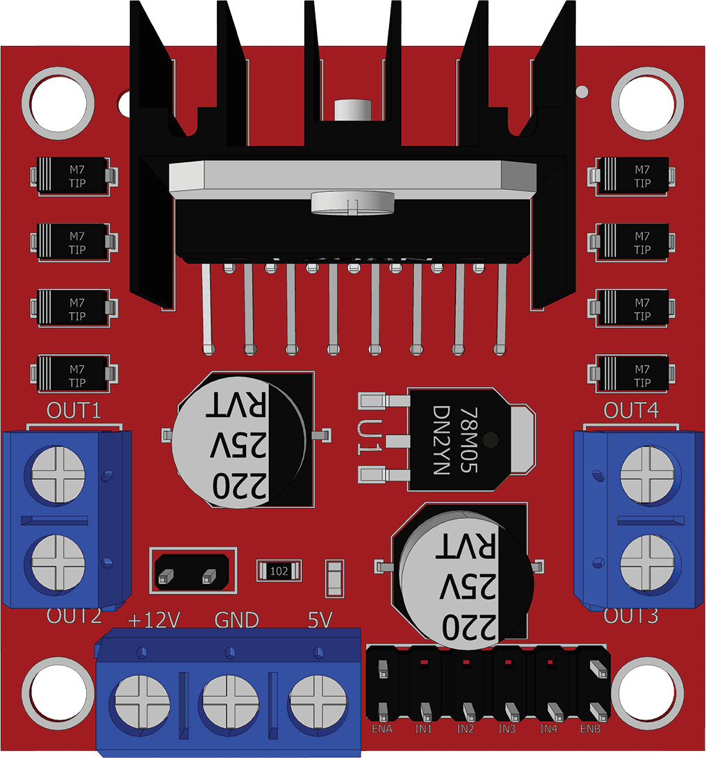
 Design with L298N in Cirkit Designer
Introduction
The L298N is a dual H-bridge motor driver that allows control of the direction and speed of DC motors and stepper motors. It can drive two motors simultaneously and is capable of handling up to 2A per channel, making it suitable for various robotics and automation applications. This versatile module is widely used in projects involving motorized systems, such as robotic arms, conveyor belts, and remote-controlled vehicles.
Explore Projects Built with L298N
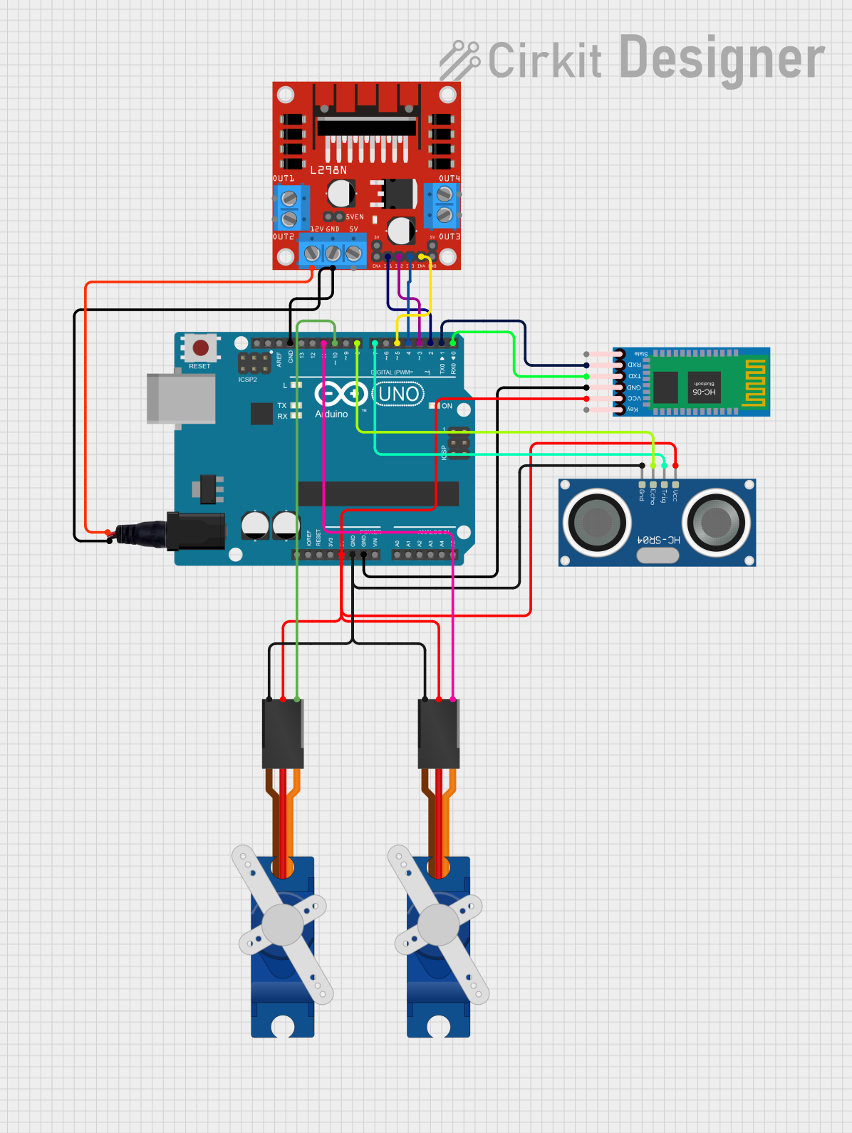 Open Project in Cirkit Designer
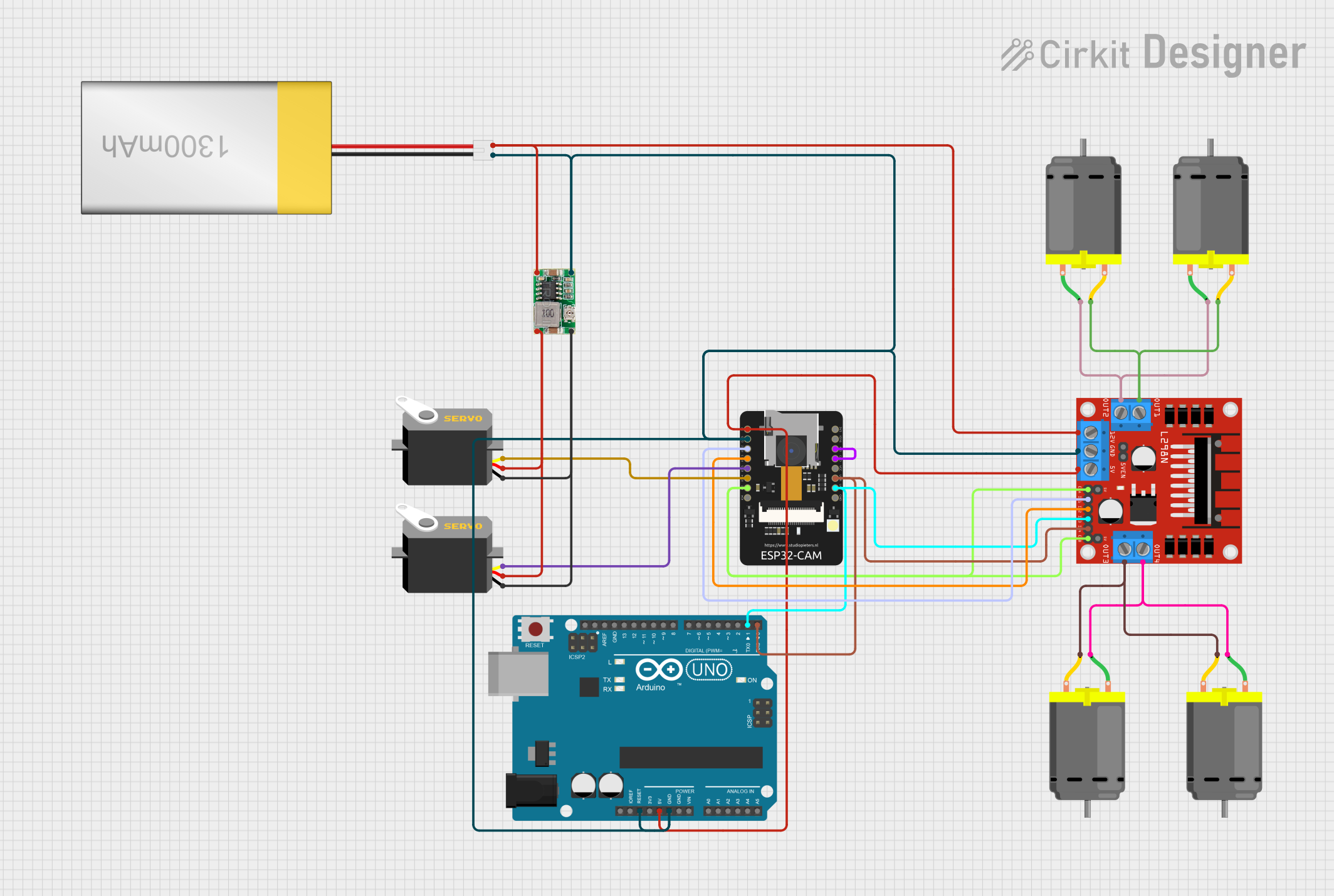 Open Project in Cirkit Designer
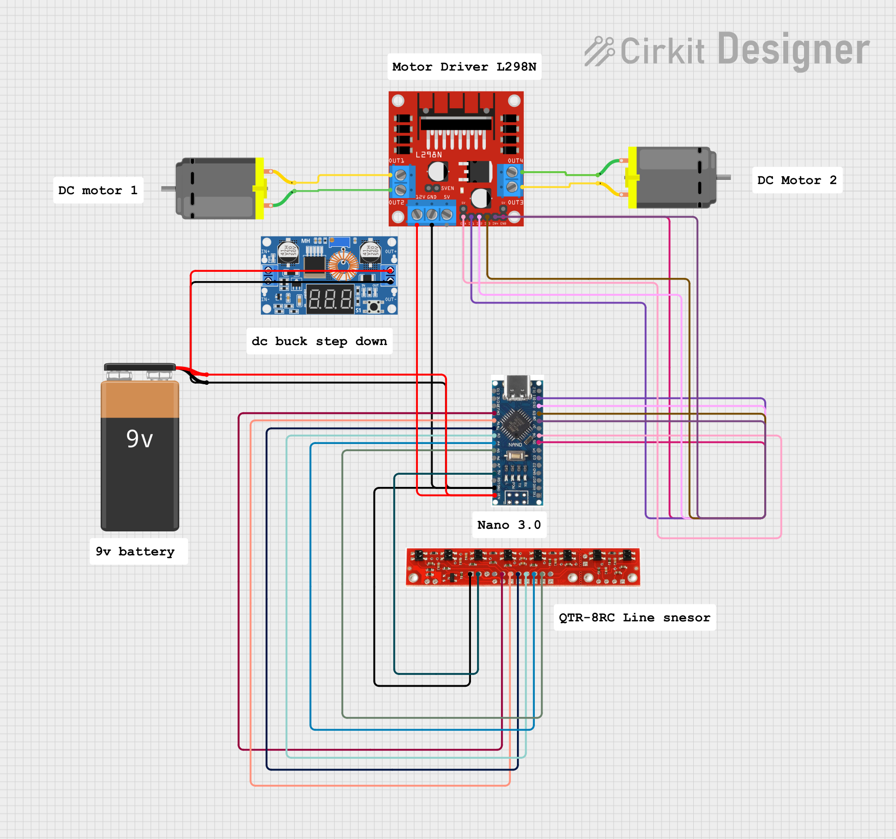 Open Project in Cirkit Designer
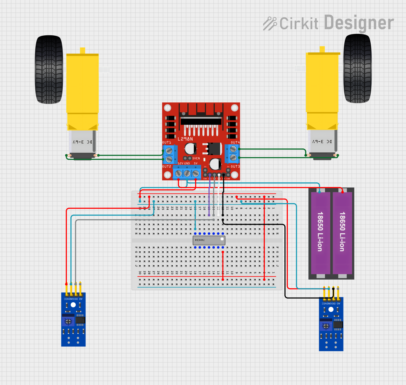 Open Project in Cirkit Designer
Explore Projects Built with L298N
Open Project in Cirkit DesignerOpen Project in Cirkit DesignerOpen Project in Cirkit DesignerOpen Project in Cirkit DesignerCommon Applications
- Robotics and automation systems
- Remote-controlled vehicles
- Conveyor belts and motorized platforms
- Stepper motor control for CNC machines and 3D printers
- DIY electronics projects involving DC motors
Technical Specifications
The L298N module is designed to simplify motor control in electronic circuits. Below are its key technical details:
Key Specifications
- Operating Voltage: 5V to 35V
- Output Current: Up to 2A per channel
- Logic Voltage: 5V
- Control Logic Levels: High (5V), Low (0V)
- Power Dissipation: 25W (with proper heat sinking)
- Number of Channels: 2 (dual H-bridge)
- Built-in Protection: Thermal shutdown and overcurrent protection
- Dimensions: Approximately 43mm x 43mm x 27mm
Pin Configuration and Descriptions
The L298N module has several pins and terminals for motor control and power input. Below is a detailed description:
Power and Motor Terminals
| Pin/Terminal | Description |
|---|---|
VCC |
Power supply for motors (5V to 35V). |
GND |
Ground connection for the module. |
5V |
Logic voltage output (used to power external logic circuits if needed). |
OUT1 |
Output for Motor A (connect to one terminal of Motor A). |
OUT2 |
Output for Motor A (connect to the other terminal of Motor A). |
OUT3 |
Output for Motor B (connect to one terminal of Motor B). |
OUT4 |
Output for Motor B (connect to the other terminal of Motor B). |
Control Pins
| Pin | Description |
|---|---|
ENA |
Enable pin for Motor A (PWM input for speed control). |
ENB |
Enable pin for Motor B (PWM input for speed control). |
IN1 |
Control input for Motor A (used to set direction). |
IN2 |
Control input for Motor A (used to set direction). |
IN3 |
Control input for Motor B (used to set direction). |
IN4 |
Control input for Motor B (used to set direction). |
Usage Instructions
The L298N module is straightforward to use in motor control applications. Below are the steps and considerations for using it effectively:
Connecting the L298N
- Power Supply: Connect the
VCCpin to a power source (5V to 35V) suitable for your motors. Connect theGNDpin to the ground of your circuit. - Motor Connections: Connect the motor terminals to
OUT1andOUT2for Motor A, andOUT3andOUT4for Motor B. - Logic Control: Connect the control pins (
IN1,IN2,IN3,IN4) to a microcontroller or other control circuit. - Enable Pins: Use the
ENAandENBpins to enable the motors. These pins can also accept PWM signals for speed control.
Controlling Motor Direction and Speed
- Direction Control: Use the
IN1andIN2pins to control the direction of Motor A, andIN3andIN4for Motor B. For example:IN1 = HIGH,IN2 = LOW: Motor A rotates forward.IN1 = LOW,IN2 = HIGH: Motor A rotates backward.IN1 = LOW,IN2 = LOW: Motor A stops.
- Speed Control: Apply a PWM signal to the
ENAorENBpins to control the speed of the motors.
Example: Using L298N with Arduino UNO
Below is an example Arduino sketch to control two DC motors using the L298N module:
// Define control pins for Motor A
#define IN1 7  // Direction control pin 1 for Motor A
#define IN2 6  // Direction control pin 2 for Motor A
#define ENA 5  // Speed control (PWM) pin for Motor A

// Define control pins for Motor B
#define IN3 4  // Direction control pin 1 for Motor B
#define IN4 3  // Direction control pin 2 for Motor B
#define ENB 2  // Speed control (PWM) pin for Motor B

void setup() {
  // Set motor control pins as outputs
  pinMode(IN1, OUTPUT);
  pinMode(IN2, OUTPUT);
  pinMode(ENA, OUTPUT);
  pinMode(IN3, OUTPUT);
  pinMode(IN4, OUTPUT);
  pinMode(ENB, OUTPUT);
}

void loop() {
  // Motor A: Forward at 50% speed
  digitalWrite(IN1, HIGH);
  digitalWrite(IN2, LOW);
  analogWrite(ENA, 128); // 50% duty cycle (0-255)

  // Motor B: Backward at 75% speed
  digitalWrite(IN3, LOW);
  digitalWrite(IN4, HIGH);
  analogWrite(ENB, 192); // 75% duty cycle (0-255)

  delay(2000); // Run motors for 2 seconds

  // Stop both motors
  digitalWrite(IN1, LOW);
  digitalWrite(IN2, LOW);
  digitalWrite(IN3, LOW);
  digitalWrite(IN4, LOW);
  analogWrite(ENA, 0);
  analogWrite(ENB, 0);

  delay(2000); // Wait for 2 seconds before repeating
}
Best Practices
- Use a heat sink on the L298N module if driving motors with high current to prevent overheating.
- Ensure the power supply voltage matches the motor's requirements.
- Use external diodes for additional protection if your motors generate significant back EMF.
Troubleshooting and FAQs
Common Issues
Motors Not Running:
- Check the power supply connections to
VCCandGND. - Ensure the
ENAandENBpins are enabled (HIGH or receiving a PWM signal). - Verify the control logic signals (
IN1,IN2,IN3,IN4) are correctly set.
- Check the power supply connections to
Overheating:
- Ensure the module has adequate heat dissipation (use a heat sink if necessary).
- Check that the motor's current does not exceed 2A per channel.
Erratic Motor Behavior:
- Verify that the power supply voltage is stable and within the specified range.
- Check for loose or faulty connections.
FAQs
Q: Can the L298N drive stepper motors?
A: Yes, the L298N can drive stepper motors by controlling the sequence of signals sent to the motor coils.
Q: What is the purpose of the 5V pin?
A: The 5V pin provides logic voltage output and can be used to power external circuits. However, if the module is powered by a 5V source, do not use this pin as an output.
Q: Can I use the L298N with a 3.3V microcontroller?
A: Yes, but you may need level shifters to ensure proper logic level compatibility.
Q: How do I control motor speed?
A: Use PWM signals on the ENA and ENB pins to control the speed of the motors.
By following this documentation, you can effectively use the L298N module in your motor control projects.