How to Use 1N4007: Examples, Pinouts, and Specs

Introduction
The 1N4007 is a widely used silicon diode that serves as a fundamental component in various electronic circuits. Its primary function is to allow current to flow in one direction while blocking it in the opposite direction, a process known as rectification. This diode is particularly common in power supply circuits where it converts alternating current (AC) to direct current (DC). Due to its high reverse voltage rating and adequate current handling capabilities, it is suitable for a range of applications including surge protection, voltage regulation, and signal demodulation.
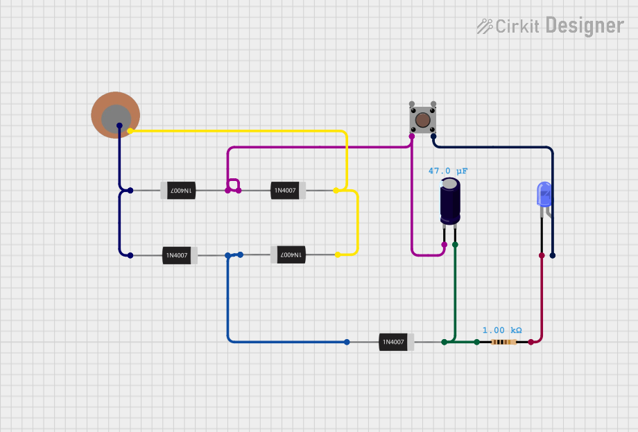
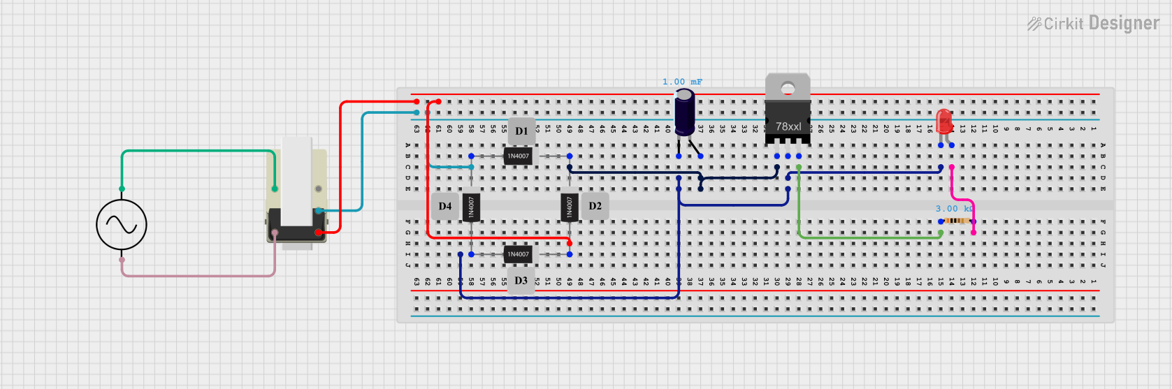
Explore Projects Built with 1N4007

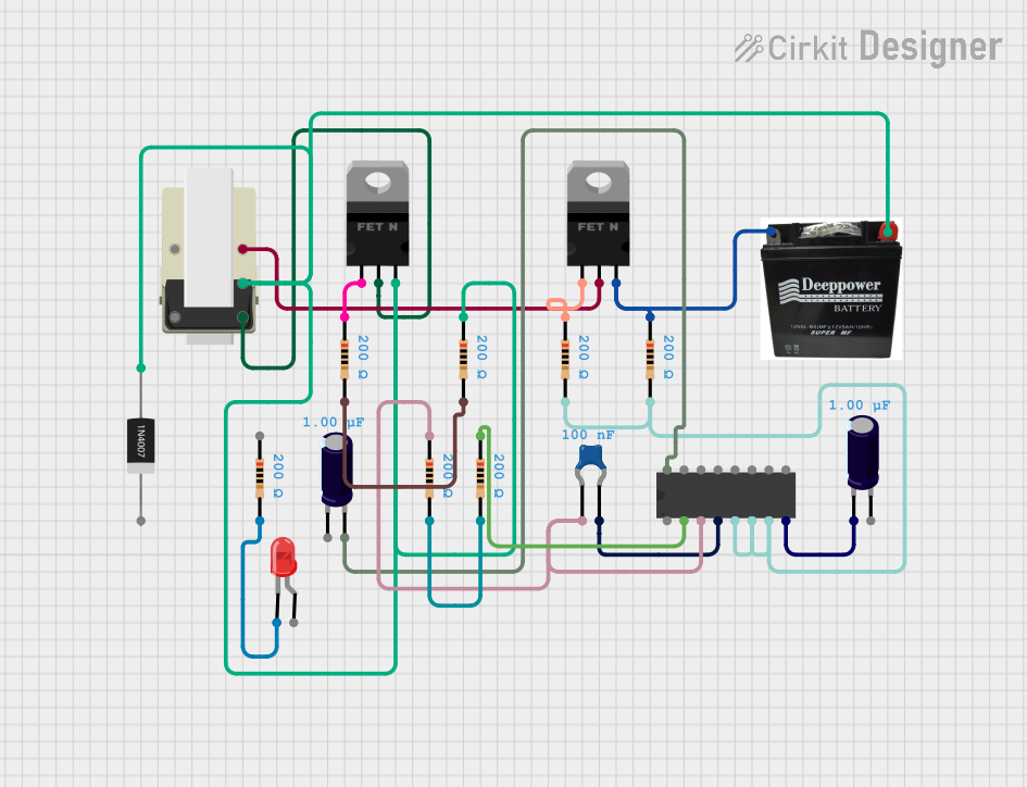
Explore Projects Built with 1N4007
Technical Specifications
Key Technical Details
- Peak Repetitive Reverse Voltage (Vrrm): 1000V
- Non-Repetitive Peak Reverse Voltage (Vrsm): 1000V
- Average Forward Current (If(av)): 1A
- Peak Forward Surge Current (Ifsm): 30A for 8.3ms
- Maximum Forward Voltage Drop (Vf): 1.1V at 1A
- Maximum DC Reverse Current (Ir): 5µA at rated Vr
- Operating Junction Temperature: -55°C to +175°C
Pin Configuration and Descriptions
| Pin Number | Name | Description |
|---|---|---|
| 1 | Anode | The positive side of the diode which current flows into. |
| 2 | Cathode | The negative side of the diode which current flows out of, marked by a band on the diode body. |
Usage Instructions
How to Use the 1N4007 in a Circuit
- Identify the Anode and Cathode: The anode is the unmarked end of the diode, while the cathode is marked with a band. Current flows from anode to cathode.
- Forward Bias Connection: To allow current flow, connect the anode to the positive voltage and the cathode to the negative side of the circuit.
- Reverse Bias Connection: To block current flow, reverse the connections. The diode will prevent current until the reverse voltage exceeds its breakdown voltage.
- Rectification: For AC to DC conversion, place the diode in series with the AC supply. The diode will only conduct on positive cycles, creating a pulsating DC output.
Important Considerations and Best Practices
- Heat Dissipation: Ensure adequate heat sinking if the diode is expected to carry currents near its rated capacity.
- Reverse Voltage Protection: Never exceed the maximum reverse voltage to prevent diode breakdown.
- Surge Current: Be cautious of surge currents that can exceed the average forward current rating, especially at power-up.
- Snubber Circuits: In inductive load applications, use a snubber circuit to protect the diode from voltage spikes.
Troubleshooting and FAQs
Common Issues
- Diode Not Conducting: Ensure the diode is forward-biased and that the voltage is sufficient to overcome the forward voltage drop.
- Diode Overheating: Check if the current exceeds the average forward current rating or if there is inadequate heat sinking.
- Unexpected Voltage Drops: Verify that the diode is not in a reverse-biased state and that it is not damaged.
Solutions and Tips for Troubleshooting
- Testing Diode Functionality: Use a multimeter in diode mode to check for proper forward and reverse bias functionality.
- Heat Management: Attach the diode to a heat sink or use a diode with a higher current rating if overheating occurs.
- Circuit Protection: Add a fuse or current-limiting resistor to protect the diode from surge currents.
FAQs
Q: Can I use the 1N4007 for high-frequency applications? A: The 1N4007 is not designed for high-frequency applications due to its relatively slow reverse recovery time. For high-frequency applications, consider using a fast-switching or Schottky diode.
Q: What happens if the reverse voltage exceeds 1000V? A: Exceeding the peak repetitive reverse voltage may lead to diode breakdown and permanent damage.
Q: Is the 1N4007 diode suitable for battery charging circuits? A: Yes, the 1N4007 can be used in battery charging circuits as a blocking diode to prevent backflow of current into the charger.
Example Code for Arduino UNO
The following example demonstrates how to use the 1N4007 diode to protect an Arduino UNO from reverse voltage when powering it through the Vin pin.
// No specific code is required for the diode itself, as it is a passive component.
// However, the diode can be included in the power supply path to the Arduino.

// Example setup:
// Connect the anode of the 1N4007 to the external power supply's positive terminal.
// Connect the cathode of the 1N4007 to the Arduino's Vin pin.
// Connect the external power supply's negative terminal to the Arduino's GND pin.

void setup() {
  // Initialize digital pin LED_BUILTIN as an output.
  pinMode(LED_BUILTIN, OUTPUT);
}

void loop() {
  // Turn the LED on (HIGH is the voltage level)
  digitalWrite(LED_BUILTIN, HIGH);
  // Wait for a second
  delay(1000);
  // Turn the LED off by making the voltage LOW
  digitalWrite(LED_BUILTIN, LOW);
  // Wait for a second
  delay(1000);
}

// Note: The diode will protect the Arduino from reverse polarity but will introduce
// a voltage drop of about 1.1V, so ensure the power supply voltage accounts for this drop.
Remember, the diode itself does not require code to operate, but it is crucial in protecting the Arduino from incorrect power connections.