
How to Use Header 6: Examples, Pinouts, and Specs
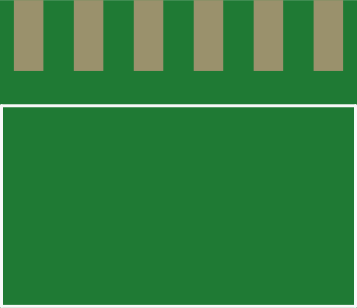
 Design with Header 6 in Cirkit Designer
Introduction
A Header 6 is a type of connector used in electronic circuits, typically featuring six pins arranged in a single or dual row. It is designed to facilitate the connection of various components or devices, enabling easy assembly, disassembly, and prototyping. Header 6 connectors are widely used in development boards, microcontrollers, and custom PCBs for interfacing peripherals or modules.
Explore Projects Built with Header 6
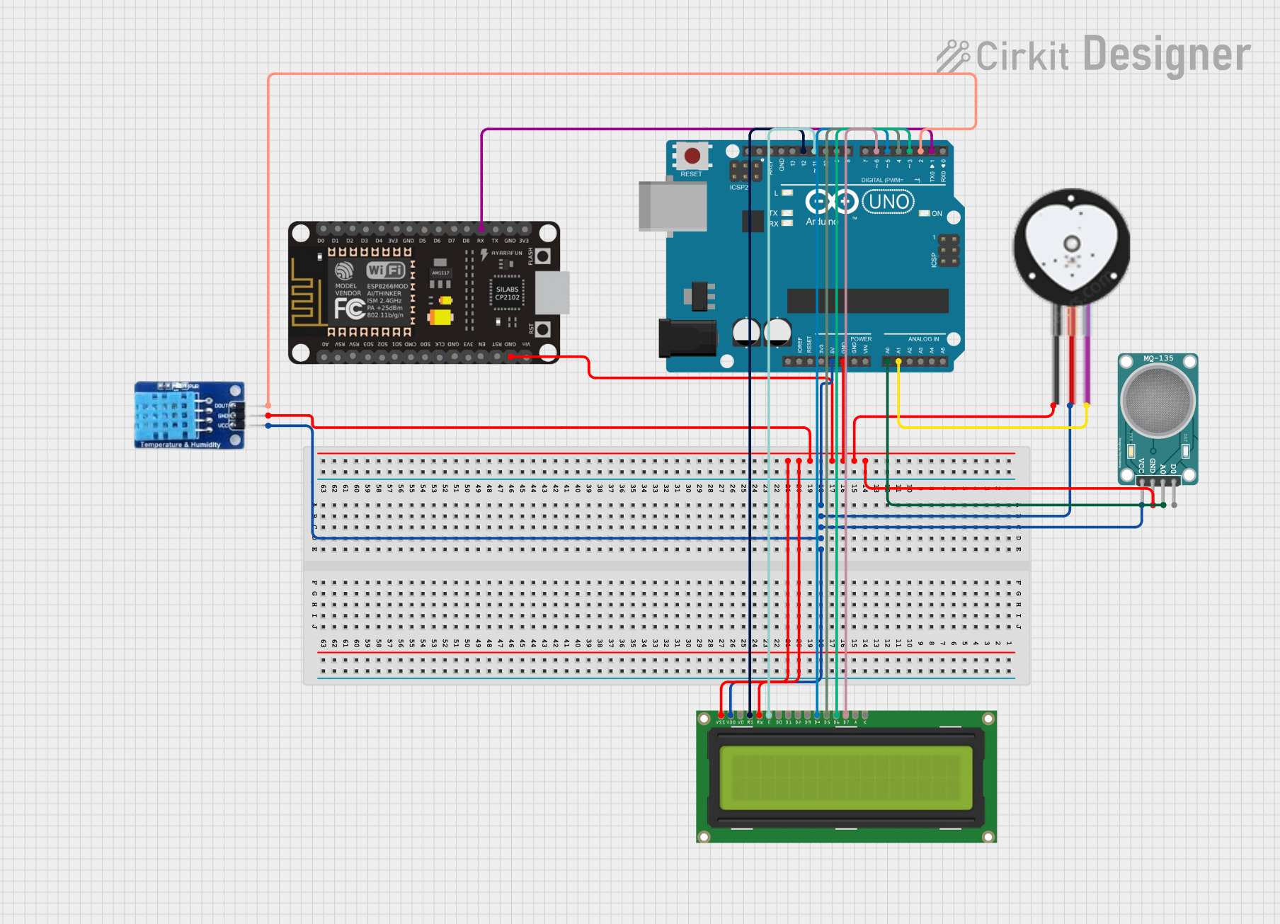 Open Project in Cirkit Designer
 Open Project in Cirkit Designer
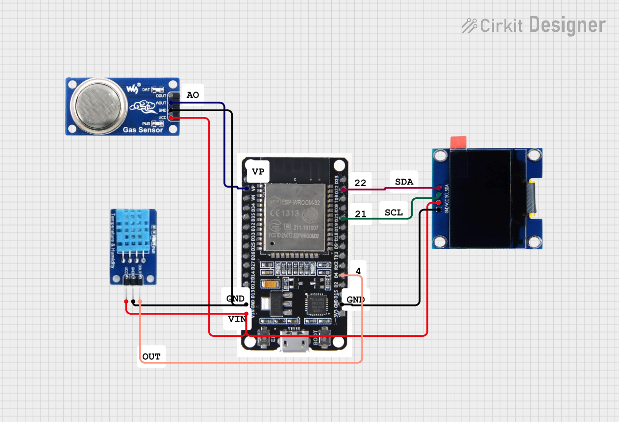 Open Project in Cirkit Designer
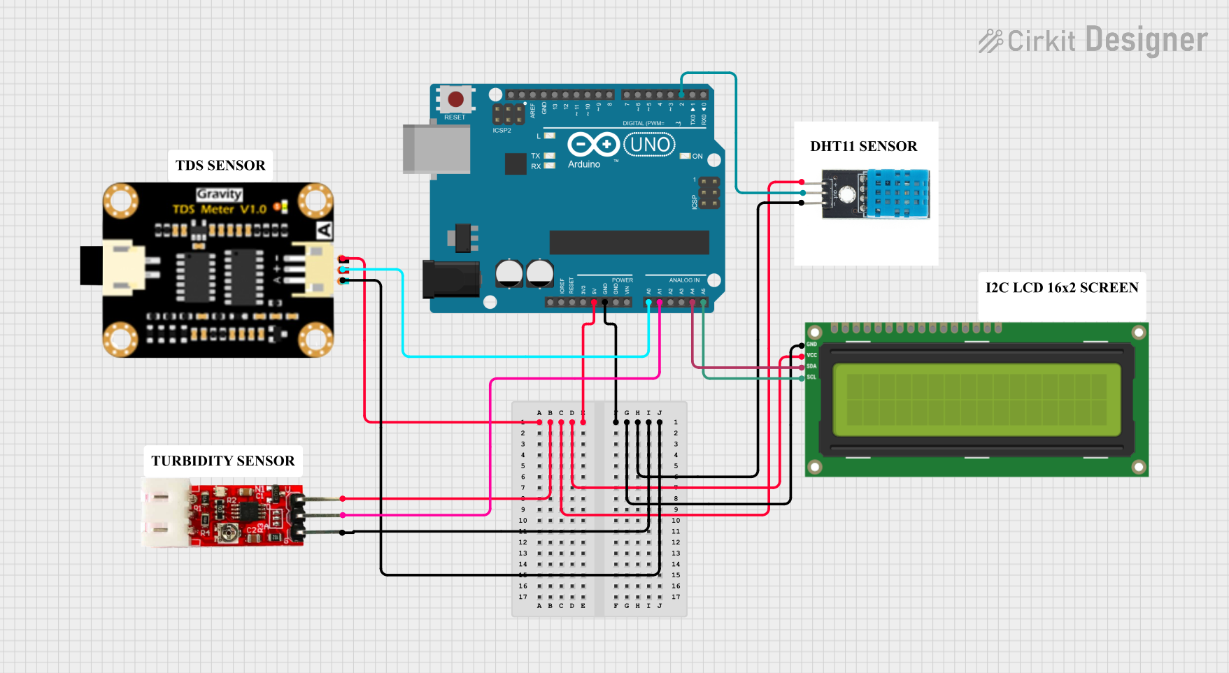 Open Project in Cirkit Designer
Explore Projects Built with Header 6
Open Project in Cirkit DesignerOpen Project in Cirkit DesignerOpen Project in Cirkit DesignerOpen Project in Cirkit DesignerCommon Applications and Use Cases
- Connecting sensors, displays, or other peripherals to microcontrollers
- Prototyping circuits on breadboards
- Interfacing with development boards like Arduino or Raspberry Pi
- Creating modular and detachable connections in electronic devices
- Extending or adapting PCB connections
Technical Specifications
Key Technical Details
- Number of Pins: 6
- Pin Pitch: 2.54 mm (standard spacing)
- Current Rating: Typically 3A per pin (varies by manufacturer)
- Voltage Rating: Up to 250V (varies by manufacturer)
- Material:
- Pins: Tin-plated or gold-plated copper
- Housing: Plastic (commonly PBT or Nylon)
- Temperature Range: -40°C to 105°C (varies by manufacturer)
- Mounting Type: Through-hole or surface-mount
Pin Configuration and Descriptions
The Header 6 connector does not have a predefined pinout, as it is a generic connector. However, the pins are typically numbered sequentially for reference in circuits. Below is an example of a single-row Header 6 pin configuration:
| Pin Number | Description | Notes |
|---|---|---|
| 1 | Signal/Power (VCC) | Can be used for power or data |
| 2 | Signal/Ground (GND) | Common ground connection |
| 3 | Signal/Data | Customizable for data signals |
| 4 | Signal/Data | Customizable for data signals |
| 5 | Signal/Data | Customizable for data signals |
| 6 | Signal/Data | Customizable for data signals |
For dual-row configurations, the pins are typically numbered alternately between rows.
Usage Instructions
How to Use the Header 6 in a Circuit
- Identify the Pinout: Determine the function of each pin in your circuit. Label the pins if necessary.
- Soldering:
- For through-hole headers, insert the pins into the PCB holes and solder them on the opposite side.
- For surface-mount headers, align the pins with the PCB pads and solder carefully.
- Connecting Components: Use jumper wires, ribbon cables, or female connectors to attach components or modules to the Header 6.
- Testing: Verify the connections with a multimeter to ensure proper continuity and avoid short circuits.
Important Considerations and Best Practices
- Pin Alignment: Ensure the pins are aligned correctly with the corresponding female connector or cable.
- Current and Voltage Ratings: Do not exceed the specified ratings to avoid damage or overheating.
- Mechanical Stress: Avoid applying excessive force when connecting or disconnecting to prevent bending or breaking the pins.
- Prototyping: Use a breadboard-compatible Header 6 for quick prototyping and testing.
Example: Connecting a Header 6 to an Arduino UNO
The Header 6 is commonly used to connect peripherals to the Arduino UNO. Below is an example of connecting a sensor module via a Header 6:
// Example: Reading data from a sensor connected via a Header 6

const int sensorPin = A0; // Pin A0 is connected to the sensor's output
int sensorValue = 0;      // Variable to store the sensor reading

void setup() {
  Serial.begin(9600); // Initialize serial communication at 9600 baud
  pinMode(sensorPin, INPUT); // Set the sensor pin as an input
}

void loop() {
  sensorValue = analogRead(sensorPin); // Read the sensor value
  Serial.print("Sensor Value: ");      // Print a label for the value
  Serial.println(sensorValue);         // Print the sensor reading
  delay(500);                          // Wait for 500ms before the next reading
}
Troubleshooting and FAQs
Common Issues Users Might Face
Loose Connections:
- Problem: The connection between the Header 6 and the female connector is loose.
- Solution: Ensure the connectors are properly aligned and seated. Replace damaged connectors if necessary.
Bent or Broken Pins:
- Problem: Pins are bent or broken due to excessive force.
- Solution: Carefully straighten bent pins with pliers. Replace the Header 6 if pins are broken.
Incorrect Pinout:
- Problem: The pinout is not correctly identified, leading to improper connections.
- Solution: Double-check the pinout and ensure it matches the circuit design.
Overheating:
- Problem: The Header 6 overheats during operation.
- Solution: Verify that the current and voltage ratings are not exceeded. Use thicker wires or connectors if necessary.
FAQs
Q1: Can I use a Header 6 for high-frequency signals?
A1: Yes, but ensure the connector and PCB layout are designed to minimize signal loss and interference.
Q2: Are Header 6 connectors compatible with breadboards?
A2: Yes, most Header 6 connectors with a 2.54 mm pitch are breadboard-compatible.
Q3: Can I cut a longer header strip to create a Header 6?
A3: Yes, you can cut a longer header strip to the desired length using wire cutters. Be careful to avoid damaging the pins.
Q4: What is the difference between male and female Header 6 connectors?
A4: Male headers have exposed pins, while female headers have sockets to receive the pins. Use the appropriate type based on your application.