How to Use GND: Examples, Pinouts, and Specs
Introduction
The ground (GND) is a reference point in an electrical circuit from which voltages are measured, and it serves as a common return path for electric current. It is a fundamental component in all electronic systems, ensuring proper operation and safety. GND is typically represented by a symbol resembling a set of horizontal lines decreasing in length.
Explore Projects Built with GND


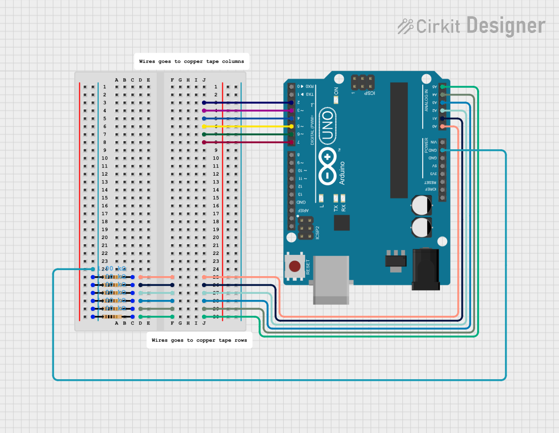
Explore Projects Built with GND
Common Applications and Use Cases
- Voltage Reference: Provides a stable reference point for measuring voltages in a circuit.
- Current Return Path: Acts as the return path for electric current in a closed circuit.
- Signal Integrity: Helps maintain signal stability and reduce noise in electronic systems.
- Safety: Protects users and components by providing a path for fault currents in case of a short circuit.
Technical Specifications
The GND pin or terminal does not have specific electrical ratings, as it is not an active component. However, its implementation in a circuit is critical for proper functionality. Below are some general considerations:
Key Technical Details
- Voltage Reference: 0V (ground potential)
- Current Handling: Depends on the circuit design and the capacity of the ground plane or wire.
- Connection Type: Typically connected to the negative terminal of a power supply or a dedicated ground plane.
Pin Configuration and Descriptions
The GND pin is commonly found on integrated circuits, microcontrollers, and other electronic components. Below is an example of how GND is represented in a typical microcontroller pinout:
| Pin Name | Description | Function |
|---|---|---|
| GND | Ground (0V reference) | Provides a common return path for current |
| VCC | Positive supply voltage | Supplies power to the component |
Usage Instructions
How to Use GND in a Circuit
- Connect to Power Supply: Ensure that the GND pin or terminal is connected to the negative terminal of the power supply.
- Establish a Common Ground: In circuits with multiple components, connect all GND pins to a common ground plane or wire to maintain a consistent reference point.
- Minimize Noise: Use a low-impedance ground connection to reduce noise and improve signal integrity.
- Safety Grounding: For devices connected to mains power, ensure proper grounding to prevent electric shock.
Important Considerations and Best Practices
- Avoid Ground Loops: Ensure that all ground connections converge at a single point to prevent ground loops, which can cause noise and interference.
- Use a Ground Plane: In PCB design, use a dedicated ground plane to improve performance and reduce electromagnetic interference (EMI).
- Check Current Capacity: Ensure that the ground connections can handle the total current flowing through the circuit.
Example: Connecting GND to an Arduino UNO
When using an Arduino UNO, the GND pin is essential for completing the circuit. Below is an example of how to connect a GND pin in a simple LED circuit:
// Example: Blinking an LED with Arduino UNO
// Connect the LED's cathode (short leg) to GND and anode (long leg) to pin 13
// through a 220-ohm resistor.

void setup() {
  pinMode(13, OUTPUT); // Set pin 13 as an output
}

void loop() {
  digitalWrite(13, HIGH); // Turn the LED on
  delay(1000);            // Wait for 1 second
  digitalWrite(13, LOW);  // Turn the LED off
  delay(1000);            // Wait for 1 second
}
Troubleshooting and FAQs
Common Issues
- No Voltage Reference: If GND is not properly connected, voltage measurements will be inaccurate or undefined.
- Solution: Verify that all components share a common ground connection.
- Noise or Interference: Poor grounding can lead to noise in the circuit.
- Solution: Use a low-impedance ground connection and avoid long ground wires.
- Ground Loops: Multiple ground paths can create loops, causing interference.
- Solution: Ensure a single-point ground connection in the circuit.
FAQs
Q: Can I connect multiple GND pins together?
A: Yes, all GND pins in a circuit should be connected to a common ground to ensure a consistent reference point.
Q: What happens if GND is not connected?
A: Without a proper ground connection, the circuit will not function correctly, and voltage levels may become undefined.
Q: How do I reduce noise in my circuit?
A: Use a dedicated ground plane, minimize the length of ground wires, and avoid ground loops.
By following these guidelines, you can ensure that GND is properly implemented in your circuits for reliable and safe operation.