Cirkit Designer Logo
Cirkit Designer
Your all-in-one circuit design IDE
Home / 
Component Documentation

How to Use ESP32-C3-0.42 OLED: Examples, Pinouts, and Specs

Image of ESP32-C3-0.42 OLED
Cirkit Designer LogoDesign with ESP32-C3-0.42 OLED in Cirkit Designer

Introduction

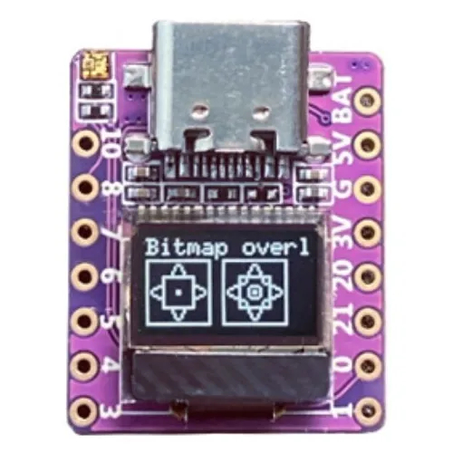
The ESP32-C3-0.42 OLED is a versatile development board designed by 01Space that combines the powerful ESP32-C3 microcontroller with a compact 0.42-inch OLED display. This board is ideal for IoT projects, wearable devices, and smart home applications where visual feedback is necessary. The integrated WiFi and Bluetooth capabilities of the ESP32-C3 allow for easy connectivity and remote data exchange.

Explore Projects Built with ESP32-C3-0.42 OLED

Use Cirkit Designer to design, explore, and prototype these projects online. Some projects support real-time simulation. Click "Open Project" to start designing instantly!
ESP32-Powered OLED Display Interface
Image of Display: A project utilizing ESP32-C3-0.42 OLED in a practical application
This circuit connects an ESP32 microcontroller to a 0.96" OLED display via I2C communication protocol. The ESP32's pins D22 and D21 are used as the serial clock (SCK) and serial data (SDA) lines, respectively, to interface with the OLED's corresponding SCK and SDA pins. The OLED is powered by the 3.3V output from the ESP32, and both devices share a common ground. The embedded code initializes the display and prints 'Hello, ESP32!' on the screen.
Cirkit Designer LogoOpen Project in Cirkit Designer
ESP32 Devkit V1 and OLED Display Bitmap Viewer
Image of Esp32_monochromeimage: A project utilizing ESP32-C3-0.42 OLED in a practical application
This circuit consists of an ESP32 Devkit V1 microcontroller connected to a 1.3" OLED display via I2C communication. The ESP32 initializes the OLED display and renders a predefined bitmap image on it.
Cirkit Designer LogoOpen Project in Cirkit Designer
ESP32-C3 Mini and OLED Display Analog Signal Visualizer
Image of Copy of scope: A project utilizing ESP32-C3-0.42 OLED in a practical application
This circuit features an ESP32-C3 Mini microcontroller connected to a 0.96" OLED display via I2C communication. The microcontroller reads analog signals from a defined analog pin, processes the data, and visualizes it as a waveform on the OLED display.
Cirkit Designer LogoOpen Project in Cirkit Designer
ESP32-C3 Mini OLED Display Analog Signal Visualizer
Image of scope: A project utilizing ESP32-C3-0.42 OLED in a practical application
This circuit features an ESP32-C3 Mini microcontroller connected to a 0.96" OLED display via I2C. The microcontroller reads an analog signal, processes it, and displays a waveform representation on the OLED screen.
Cirkit Designer LogoOpen Project in Cirkit Designer

Explore Projects Built with ESP32-C3-0.42 OLED

Use Cirkit Designer to design, explore, and prototype these projects online. Some projects support real-time simulation. Click "Open Project" to start designing instantly!
Image of Display: A project utilizing ESP32-C3-0.42 OLED in a practical application
ESP32-Powered OLED Display Interface
This circuit connects an ESP32 microcontroller to a 0.96" OLED display via I2C communication protocol. The ESP32's pins D22 and D21 are used as the serial clock (SCK) and serial data (SDA) lines, respectively, to interface with the OLED's corresponding SCK and SDA pins. The OLED is powered by the 3.3V output from the ESP32, and both devices share a common ground. The embedded code initializes the display and prints 'Hello, ESP32!' on the screen.
Cirkit Designer LogoOpen Project in Cirkit Designer
Image of Esp32_monochromeimage: A project utilizing ESP32-C3-0.42 OLED in a practical application
ESP32 Devkit V1 and OLED Display Bitmap Viewer
This circuit consists of an ESP32 Devkit V1 microcontroller connected to a 1.3" OLED display via I2C communication. The ESP32 initializes the OLED display and renders a predefined bitmap image on it.
Cirkit Designer LogoOpen Project in Cirkit Designer
Image of Copy of scope: A project utilizing ESP32-C3-0.42 OLED in a practical application
ESP32-C3 Mini and OLED Display Analog Signal Visualizer
This circuit features an ESP32-C3 Mini microcontroller connected to a 0.96" OLED display via I2C communication. The microcontroller reads analog signals from a defined analog pin, processes the data, and visualizes it as a waveform on the OLED display.
Cirkit Designer LogoOpen Project in Cirkit Designer
Image of scope: A project utilizing ESP32-C3-0.42 OLED in a practical application
ESP32-C3 Mini OLED Display Analog Signal Visualizer
This circuit features an ESP32-C3 Mini microcontroller connected to a 0.96" OLED display via I2C. The microcontroller reads an analog signal, processes it, and displays a waveform representation on the OLED screen.
Cirkit Designer LogoOpen Project in Cirkit Designer

Technical Specifications

General Features

  • Microcontroller: ESP32-C3
  • Display: 0.42-inch OLED
  • Connectivity: WiFi 802.11 b/g/n, Bluetooth 4.2/5.0 LE
  • Flash Memory: 4MB
  • SRAM: 400 KB
  • GPIO Pins: 22
  • ADC Channels: 6
  • Operating Voltage: 3.3V
  • Operating Temperature: -40°C to +85°C

Pin Configuration

Pin Number Function Description
1 3V3 Power supply (3.3V input)
2 GND Ground
3 EN Chip enable. Active high.
4 IO0 General-purpose I/O and/or programming pin
... ... ...
n IO21 General-purpose I/O pin

Note: The full pinout will be provided by the manufacturer or can be found in the detailed datasheet.

Usage Instructions

Interfacing with the OLED Display

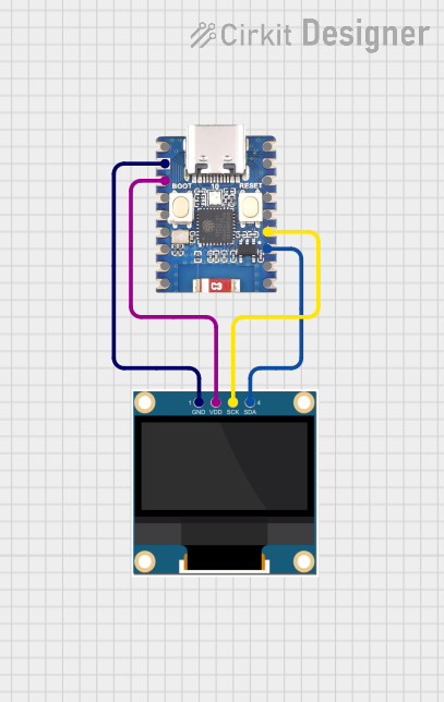
To use the 0.42-inch OLED display, you'll need to connect it to the ESP32-C3's I2C pins. Here's a simple example of how to wire the display to the ESP32-C3:

  • OLED SDA (Serial Data) -> ESP32-C3 IOx (configured as I2C SDA)
  • OLED SCL (Serial Clock) -> ESP32-C3 IOy (configured as I2C SCL)
  • OLED VCC -> 3V3
  • OLED GND -> GND

Programming the ESP32-C3

  1. Install the required drivers for the USB-to-UART bridge chip used on the board.
  2. Use the Arduino IDE or ESP-IDF to write and upload your code to the ESP32-C3.
  3. Ensure the board is in bootloading mode if necessary (usually by holding the BOOT button while resetting the board).

Best Practices

  • Always disconnect the board from power before making or altering connections.
  • Use a logic level converter if interfacing with components that operate at different voltage levels.
  • Avoid drawing too much current from the GPIO pins to prevent damage to the board.

Example Code for Arduino UNO

#include <Wire.h>
#include <Adafruit_GFX.h>
#include <Adafruit_SSD1306.h>

#define SCREEN_WIDTH 128 // OLED display width, in pixels
#define SCREEN_HEIGHT 32 // OLED display height, in pixels

// Declaration for an SSD1306 display connected to I2C (SDA, SCL pins)
#define OLED_RESET     -1 // Reset pin # (or -1 if sharing Arduino reset pin)
Adafruit_SSD1306 display(SCREEN_WIDTH, SCREEN_HEIGHT, &Wire, OLED_RESET);

void setup() {
  // Initialize OLED display
  if(!display.begin(SSD1306_SWITCHCAPVCC, 0x3C)) { 
    Serial.println(F("SSD1306 allocation failed"));
    for(;;);
  }
  display.display();
  delay(2000); // Pause for 2 seconds

  // Clear the buffer
  display.clearDisplay();

  // Draw a single pixel in white
  display.drawPixel(10, 10, SSD1306_WHITE);

  // Display the drawing
  display.display();
}

void loop() {
  // Code to update the display continuously
}

Note: The above code is for interfacing with a generic SSD1306 OLED display using the Adafruit SSD1306 library. Adjust the I2C address (0x3C) and screen dimensions if necessary for the specific OLED model on the ESP32-C3-0.42 OLED board.

Troubleshooting and FAQs

Common Issues

  • Display not lighting up: Ensure that the OLED is correctly wired to the ESP32-C3 and that the I2C address matches the one in your code.
  • WiFi/Bluetooth not functioning: Check that the antenna is properly connected and that your code correctly initializes the WiFi/Bluetooth module.
  • Board not recognized by computer: Verify that the correct drivers are installed and that the USB cable is functioning.

FAQs

Q: Can I power the ESP32-C3-0.42 OLED with a battery? A: Yes, you can power it with a battery, but ensure that the voltage is regulated to 3.3V.

Q: What is the maximum current draw from a GPIO pin? A: The maximum current per I/O pin should not exceed 12 mA.

Q: How do I update the firmware on the ESP32-C3? A: Firmware updates can be done through the UART interface using the bootloader mode or over-the-air (OTA) if your code supports it.

For further assistance, consult the manufacturer's documentation or contact 01Space support.