How to Use Right Servo: Examples, Pinouts, and Specs
Introduction
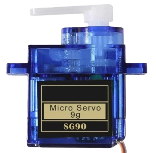
A right servo is a type of motor designed for precise angular control. Unlike standard DC motors, which rotate continuously, a servo motor can be controlled to move to a specific angle within its range of motion. This makes it an essential component in robotics, automation, and other applications requiring accurate positioning. Right servos are commonly used in robotic arms, RC vehicles, automated systems, and hobbyist projects.
Explore Projects Built with Right Servo


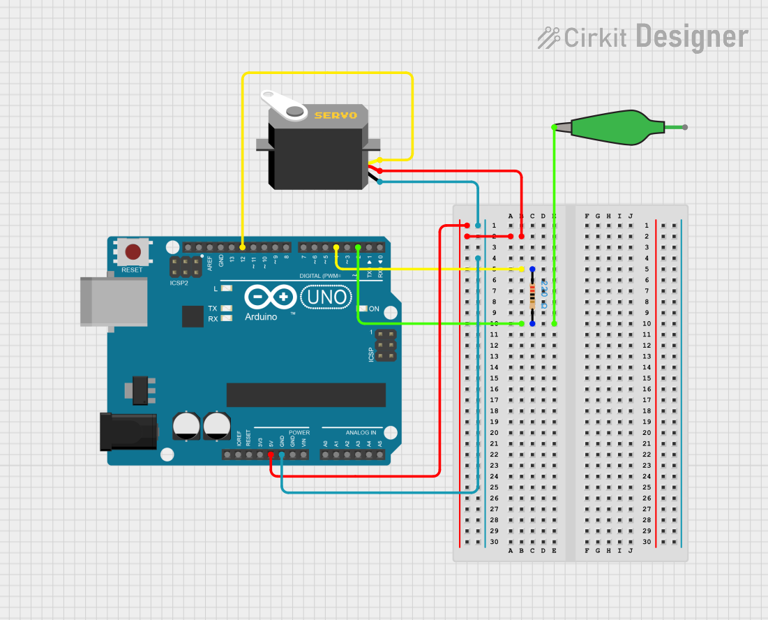
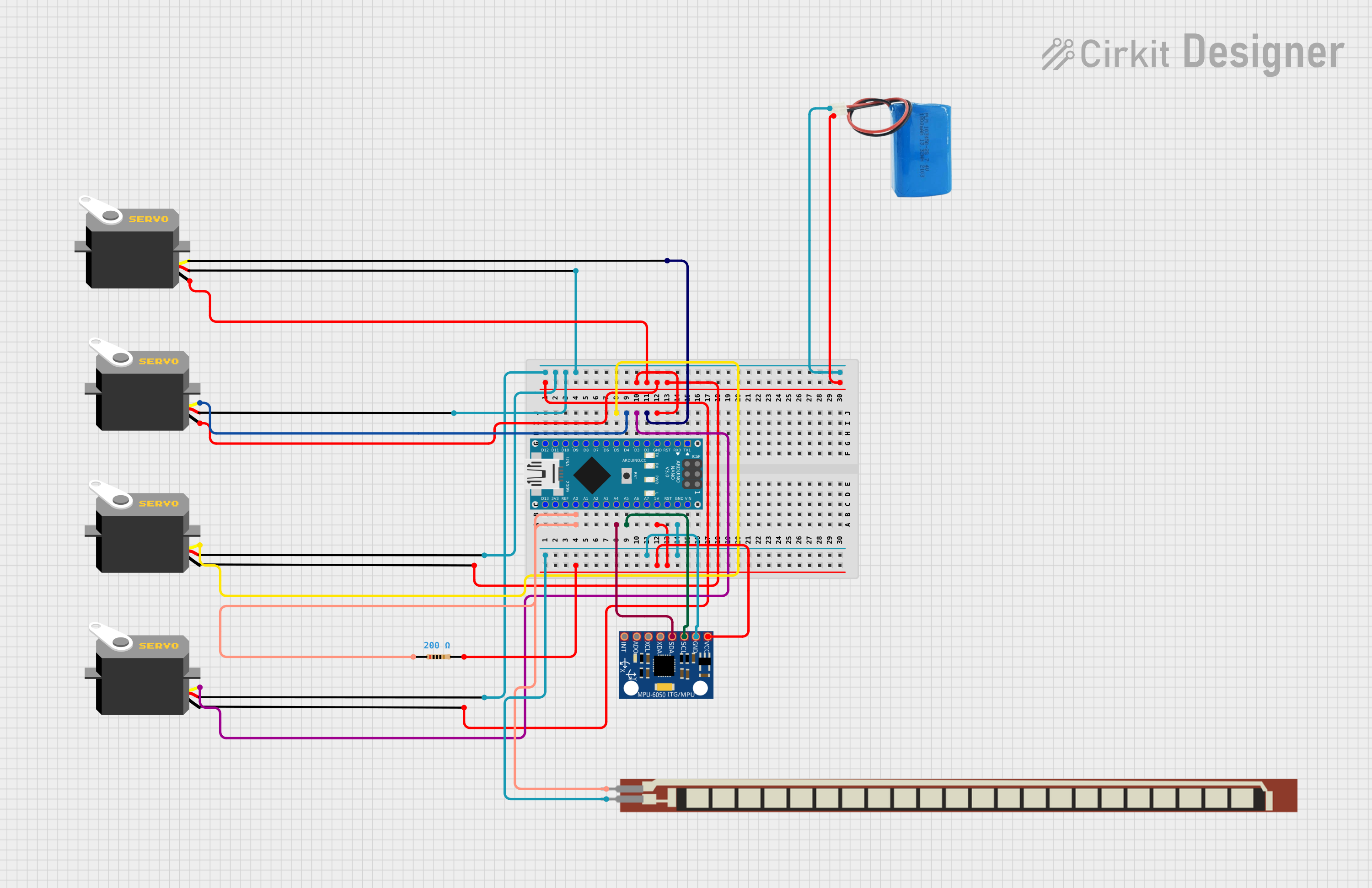
Explore Projects Built with Right Servo
Technical Specifications
Below are the key technical details for a typical right servo motor:
| Parameter | Value |
|---|---|
| Operating Voltage | 4.8V to 6.0V |
| Stall Torque | 1.5 kg·cm to 3.0 kg·cm (varies) |
| Operating Speed | ~0.1s/60° at 6.0V |
| Control Signal | PWM (Pulse Width Modulation) |
| PWM Signal Range | 500 µs to 2500 µs |
| Rotation Range | 0° to 180° |
| Idle Current | ~10 mA |
| Maximum Current | ~1.5 A (under load) |
| Connector Type | 3-pin (Signal, VCC, GND) |
Pin Configuration
The right servo typically has a 3-pin connector. The table below describes each pin:
| Pin | Wire Color | Description |
|---|---|---|
| Signal | Orange/White | Receives PWM control signal |
| VCC | Red | Power supply (4.8V to 6.0V) |
| GND | Black/Brown | Ground connection |
Usage Instructions
How to Use the Right Servo in a Circuit
- Power Supply: Connect the VCC pin to a 5V power source and the GND pin to the ground of your circuit. Ensure the power supply can handle the current requirements of the servo.
- Control Signal: Connect the Signal pin to a PWM-capable pin on your microcontroller (e.g., Arduino).
- PWM Signal: Use a PWM signal to control the servo's position. A pulse width of 1 ms typically corresponds to 0°, 1.5 ms to 90°, and 2 ms to 180°.
Important Considerations
- Power Supply: Avoid powering the servo directly from the microcontroller's 5V pin, as it may not provide sufficient current. Use an external power source if necessary.
- Signal Stability: Ensure the PWM signal is stable to prevent jittery or erratic movements.
- Mechanical Limits: Do not force the servo beyond its physical rotation range (0° to 180°), as this can damage the internal gears.
Example: Connecting a Right Servo to an Arduino UNO
Below is an example Arduino sketch to control a right servo:
#include <Servo.h> // Include the Servo library

Servo rightServo; // Create a Servo object

void setup() {
  rightServo.attach(9); // Attach the servo to pin 9
}

void loop() {
  rightServo.write(0); // Move servo to 0 degrees
  delay(1000);         // Wait for 1 second

  rightServo.write(90); // Move servo to 90 degrees
  delay(1000);          // Wait for 1 second

  rightServo.write(180); // Move servo to 180 degrees
  delay(1000);           // Wait for 1 second
}
Best Practices
- Use a capacitor across the power supply to reduce noise and voltage fluctuations.
- Avoid sudden changes in position to reduce wear on the servo's gears.
- Test the servo with no load before integrating it into your project.
Troubleshooting and FAQs
Common Issues and Solutions
Servo Not Moving:
- Cause: Incorrect wiring or insufficient power supply.
- Solution: Double-check the connections and ensure the power source meets the servo's voltage and current requirements.
Jittery or Erratic Movement:
- Cause: Unstable PWM signal or electrical noise.
- Solution: Use a decoupling capacitor across the power supply and ensure the PWM signal is clean.
Servo Overheating:
- Cause: Prolonged operation under heavy load.
- Solution: Reduce the load or allow the servo to cool down periodically.
Limited Range of Motion:
- Cause: Incorrect PWM signal range or mechanical obstruction.
- Solution: Verify the PWM signal range and ensure there are no physical obstructions.
FAQs
Q: Can I use the right servo with a 3.3V microcontroller?
A: Yes, but you must ensure the servo's control signal is compatible with 3.3V logic levels. Alternatively, use a level shifter.
Q: How do I know if my servo is receiving the correct PWM signal?
A: Use an oscilloscope to verify the pulse width of the PWM signal matches the desired angle.
Q: Can I rotate the servo beyond 180°?
A: No, most standard right servos are limited to a 0° to 180° range. For continuous rotation, use a modified or continuous rotation servo.
Q: Why does my servo make a buzzing noise?
A: This is usually caused by the servo trying to hold its position under load. Ensure the load is within the servo's torque rating.