Cirkit Designer Logo
Cirkit Designer
Your all-in-one circuit design IDE
Home / 
Component Documentation

How to Use ULN2003A breakout board: Examples, Pinouts, and Specs

Image of ULN2003A breakout board
Cirkit Designer LogoDesign with ULN2003A breakout board in Cirkit Designer

Introduction

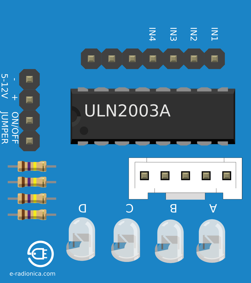
The ULN2003A breakout board is a compact and efficient solution for driving high-current loads with low-voltage control signals. It features the ULN2003A integrated circuit, which contains seven NPN Darlington pairs capable of handling up to 500mA per channel with a maximum voltage of 50V. This breakout board is commonly used in applications such as stepper motor driving, relay control, and solenoid actuation.

Explore Projects Built with ULN2003A breakout board

Use Cirkit Designer to design, explore, and prototype these projects online. Some projects support real-time simulation. Click "Open Project" to start designing instantly!
Battery-Powered Arduino UNO and ESP-8266 Smart Controller with LCD and RTC
Image of Ogie Diagram: A project utilizing ULN2003A breakout board in a practical application
This circuit is a power management and control system that uses a 12V power supply and a 18650 Li-ion battery pack to provide a stable 5V output through a step-down buck converter. It includes an Arduino UNO, an ESP-8266 controller, a DS1307 RTC module, and a 20x4 I2C LCD display for monitoring and control purposes. The ULN2003A breakout board is used for driving higher current loads.
Cirkit Designer LogoOpen Project in Cirkit Designer
Arduino Nano Controlled Dual Stepper Motor and Servo System
Image of nano plus servo: A project utilizing ULN2003A breakout board in a practical application
This circuit controls two 28BYJ-48 stepper motors and a micro servo using an Arduino Nano. The ULN2003A breakout boards interface the stepper motors with the Arduino, while the micro servo is directly controlled via a PWM signal from the Arduino. Power is supplied through a 2.1mm DC barrel jack.
Cirkit Designer LogoOpen Project in Cirkit Designer
Arduino Mega 2560 Controlled Multi-Stepper Motor System
Image of vendopharma circuit: A project utilizing ULN2003A breakout board in a practical application
This circuit is designed to control multiple 28BYJ-48 stepper motors using ULN2003A breakout boards, with an Arduino Mega 2560 serving as the central controller. The Arduino's digital pins are connected to the input pins of the ULN2003A boards to drive the stepper motors. Power is supplied to the breakout boards through the Arduino's 5V and GND pins, and the stepper motors are connected to their respective breakout boards.
Cirkit Designer LogoOpen Project in Cirkit Designer
Arduino Mega 2560 Smart Home Automation System with LCD Display and Sensor Integration
Image of CPE_301_FINAL: A project utilizing ULN2003A breakout board in a practical application
This circuit is a multi-functional system controlled by an Arduino Mega 2560, featuring an LCD display, various LEDs, a stepper motor, a DC motor, and multiple sensors including a DHT11 humidity and temperature sensor and a water level sensor. The system also includes a real-time clock module for timekeeping and several pushbuttons for user interaction. The ULN2003A breakout board is used to drive the stepper motor, while the L293D motor driver controls the DC motor.
Cirkit Designer LogoOpen Project in Cirkit Designer

Explore Projects Built with ULN2003A breakout board

Use Cirkit Designer to design, explore, and prototype these projects online. Some projects support real-time simulation. Click "Open Project" to start designing instantly!
Image of Ogie Diagram: A project utilizing ULN2003A breakout board in a practical application
Battery-Powered Arduino UNO and ESP-8266 Smart Controller with LCD and RTC
This circuit is a power management and control system that uses a 12V power supply and a 18650 Li-ion battery pack to provide a stable 5V output through a step-down buck converter. It includes an Arduino UNO, an ESP-8266 controller, a DS1307 RTC module, and a 20x4 I2C LCD display for monitoring and control purposes. The ULN2003A breakout board is used for driving higher current loads.
Cirkit Designer LogoOpen Project in Cirkit Designer
Image of nano plus servo: A project utilizing ULN2003A breakout board in a practical application
Arduino Nano Controlled Dual Stepper Motor and Servo System
This circuit controls two 28BYJ-48 stepper motors and a micro servo using an Arduino Nano. The ULN2003A breakout boards interface the stepper motors with the Arduino, while the micro servo is directly controlled via a PWM signal from the Arduino. Power is supplied through a 2.1mm DC barrel jack.
Cirkit Designer LogoOpen Project in Cirkit Designer
Image of vendopharma circuit: A project utilizing ULN2003A breakout board in a practical application
Arduino Mega 2560 Controlled Multi-Stepper Motor System
This circuit is designed to control multiple 28BYJ-48 stepper motors using ULN2003A breakout boards, with an Arduino Mega 2560 serving as the central controller. The Arduino's digital pins are connected to the input pins of the ULN2003A boards to drive the stepper motors. Power is supplied to the breakout boards through the Arduino's 5V and GND pins, and the stepper motors are connected to their respective breakout boards.
Cirkit Designer LogoOpen Project in Cirkit Designer
Image of CPE_301_FINAL: A project utilizing ULN2003A breakout board in a practical application
Arduino Mega 2560 Smart Home Automation System with LCD Display and Sensor Integration
This circuit is a multi-functional system controlled by an Arduino Mega 2560, featuring an LCD display, various LEDs, a stepper motor, a DC motor, and multiple sensors including a DHT11 humidity and temperature sensor and a water level sensor. The system also includes a real-time clock module for timekeeping and several pushbuttons for user interaction. The ULN2003A breakout board is used to drive the stepper motor, while the L293D motor driver controls the DC motor.
Cirkit Designer LogoOpen Project in Cirkit Designer

Common Applications and Use Cases

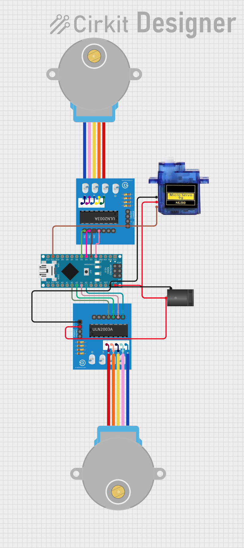
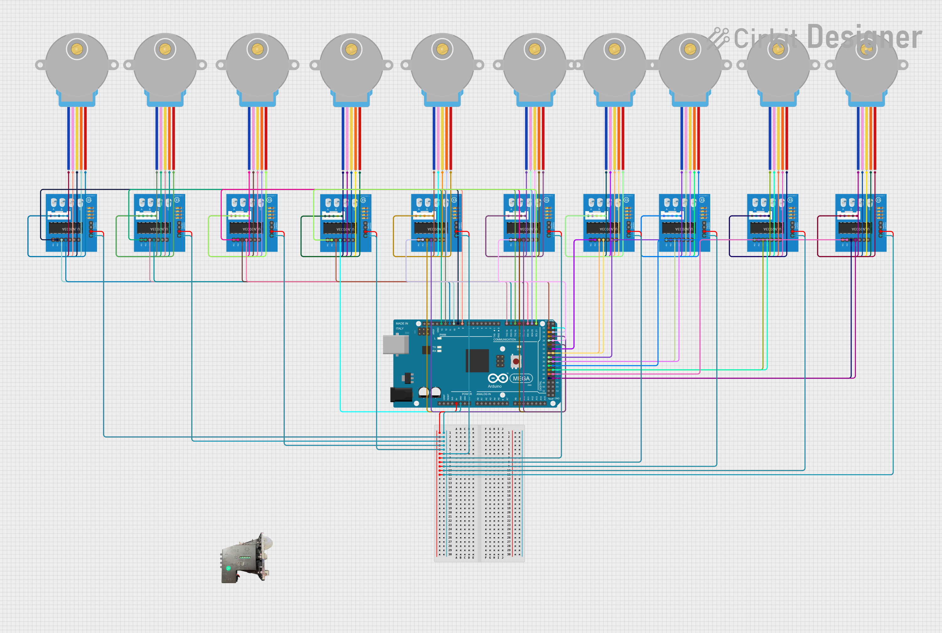
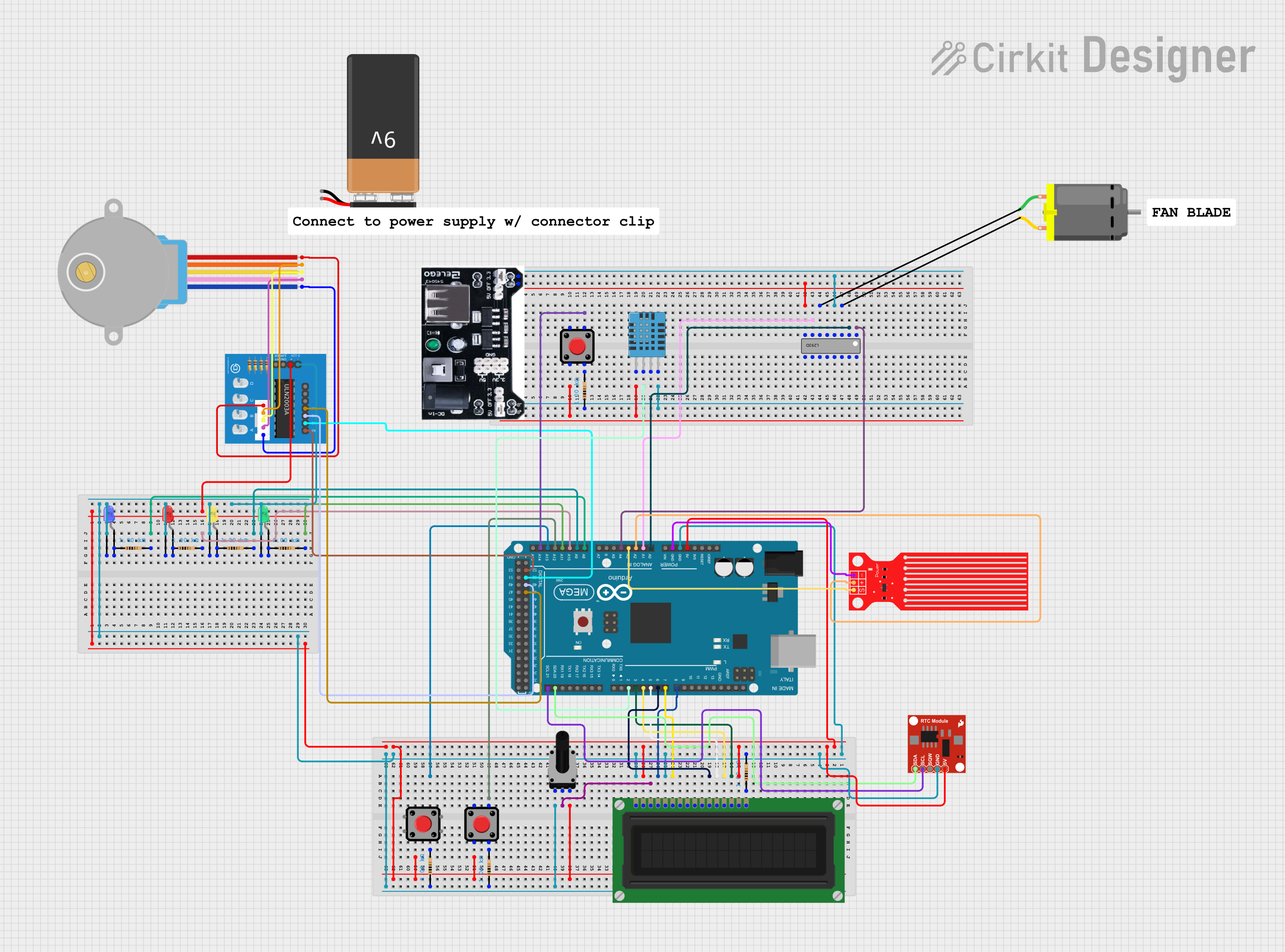
  • Stepper motor driving for 3D printers, CNC machines, and robotics
  • Relay control for home automation and industrial equipment
  • Solenoid actuation in vending machines and locking mechanisms
  • LED array driving for signage and decorative lighting

Technical Specifications

Key Technical Details

  • Operating Voltage (Vcc): 5V typical (up to 50V max)
  • Output Current (per channel): 500mA max
  • Peak Output Current (per channel): 600mA
  • Input Voltage (Logic Level): 3.3V to 5V
  • Clamping Voltage: 50V (max)
  • Mounting Type: Through-hole

Pin Configuration and Descriptions

Pin Number Pin Name Description
1 IN1 Input for Channel 1
2 IN2 Input for Channel 2
3 IN3 Input for Channel 3
4 IN4 Input for Channel 4
5 IN5 Input for Channel 5
6 IN6 Input for Channel 6
7 IN7 Input for Channel 7
8 GND Ground
9 COM Common free-wheeling diodes
10 OUT1 Output for Channel 1
11 OUT2 Output for Channel 2
12 OUT3 Output for Channel 3
13 OUT4 Output for Channel 4
14 OUT5 Output for Channel 5
15 OUT6 Output for Channel 6
16 OUT7 Output for Channel 7

Usage Instructions

How to Use the Component in a Circuit

  1. Connect the input pins (IN1-IN7) to the control signals from your microcontroller.
  2. Connect the output pins (OUT1-OUT7) to the loads you wish to drive.
  3. Connect the COM pin to the positive voltage supply if using inductive loads.
  4. Ensure the GND pin is connected to the ground of your control circuit.
  5. Apply the control signals to the input pins to activate the corresponding outputs.

Important Considerations and Best Practices

  • Use a current limiting resistor on the input if the control signal exceeds the recommended input voltage.
  • Ensure the total current through all outputs does not exceed the maximum rating of the IC.
  • Use external flyback diodes for inductive loads if the internal diodes do not meet the requirements.
  • Avoid operating the breakout board at its maximum ratings for extended periods to prevent overheating and ensure longevity.

Example Code for Arduino UNO

// Define the input pins connected to the ULN2003A
const int inputPins[] = {2, 3, 4, 5, 6, 7, 8};

void setup() {
  // Set all the input pins as outputs
  for (int i = 0; i < 7; i++) {
    pinMode(inputPins[i], OUTPUT);
  }
}

void loop() {
  // Activate each channel in sequence
  for (int i = 0; i < 7; i++) {
    digitalWrite(inputPins[i], HIGH); // Turn on the channel
    delay(1000);                      // Wait for 1 second
    digitalWrite(inputPins[i], LOW);  // Turn off the channel
  }
}

Troubleshooting and FAQs

Common Issues Users Might Face

  • Outputs not activating: Ensure that the input signals are within the correct voltage range and that the GND and COM pins are properly connected.
  • Overheating: Check if the current through the channels is within the specified limits and that the board is not operating at maximum ratings continuously.
  • Unexpected behavior with inductive loads: Verify that the COM pin is connected to the supply voltage and that external diodes are used if necessary.

Solutions and Tips for Troubleshooting

  • Double-check wiring and connections for any loose or incorrect connections.
  • Use a multimeter to verify the input signal voltage and the continuity of the output load circuit.
  • Implement a test code that sequentially activates each channel to isolate and identify any issues with specific channels or loads.

FAQs

Q: Can I drive a load that requires more than 500mA? A: No, each channel can only handle up to 500mA. For higher currents, consider using a different driver or parallel connections with proper current sharing.

Q: Is it necessary to use external flyback diodes with inductive loads? A: The ULN2003A has built-in flyback diodes for common inductive loads. However, for loads with higher inductive kickback, external diodes may be necessary.

Q: Can I control the ULN2003A with a 3.3V logic level? A: Yes, the ULN2003A can be controlled with 3.3V logic levels, making it compatible with a wide range of microcontrollers.

Q: How can I dissipate heat from the ULN2003A if I'm driving loads near the maximum current rating? A: Attach a heat sink to the ULN2003A or ensure adequate airflow around the breakout board to help dissipate heat.