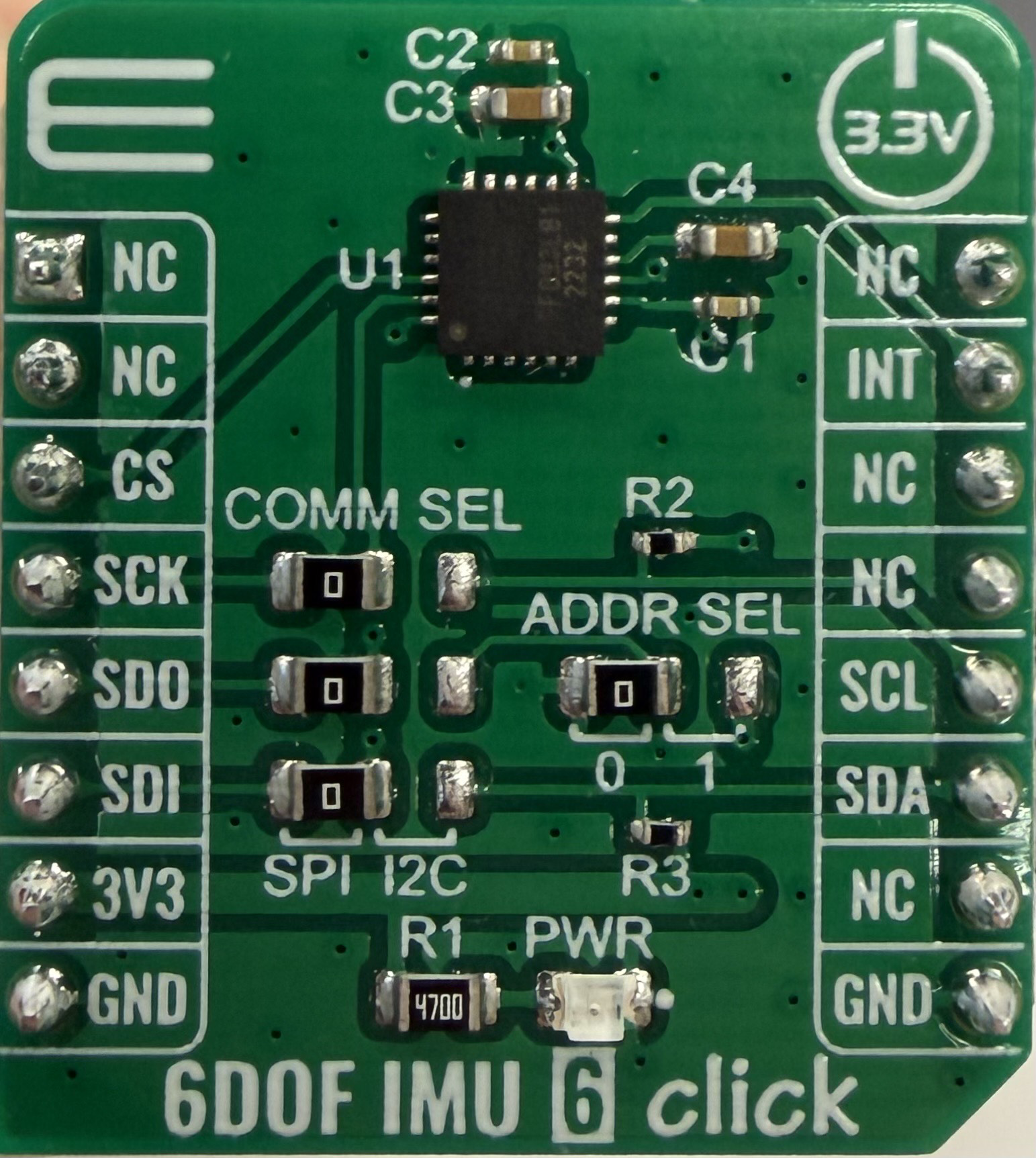
How to Use 6DOF IMU 6 Click: Examples, Pinouts, and Specs
Introduction
The 6DOF IMU 6 Click (Manufacturer Part ID: MIKROE-4044) is a compact module developed by MikroElektronika. It integrates a 6-axis Inertial Measurement Unit (IMU) that combines a 3-axis accelerometer and a 3-axis gyroscope. This module is designed for precise motion tracking and orientation sensing, making it ideal for applications such as robotics, drones, gaming devices, and industrial equipment.
The 6DOF IMU 6 Click is based on the IIS2ICLX sensor from STMicroelectronics, which offers high accuracy, low power consumption, and advanced features for motion detection and vibration monitoring.
Explore Projects Built with 6DOF IMU 6 Click


Explore Projects Built with 6DOF IMU 6 Click
Common Applications
- Robotics and autonomous systems
- Drone stabilization and navigation
- Wearable devices and fitness trackers
- Gaming controllers and virtual reality systems
- Industrial equipment monitoring and vibration analysis
Technical Specifications
Key Technical Details
| Parameter | Value |
|---|---|
| Sensor Type | 6-axis IMU (3-axis accelerometer + 3-axis gyroscope) |
| Communication Interface | I2C, SPI |
| Operating Voltage | 3.3V |
| Accelerometer Range | ±2g, ±4g, ±8g, ±16g |
| Gyroscope Range | ±125°/s, ±250°/s, ±500°/s, ±1000°/s, ±2000°/s |
| Output Data Rate (ODR) | Up to 6660 Hz |
| Operating Temperature | -40°C to +85°C |
| Dimensions | 28.6mm x 25.4mm |
Pin Configuration and Descriptions
The 6DOF IMU 6 Click uses a standard mikroBUS™ socket for easy integration. The pinout is as follows:
| Pin No. | Pin Name | Description |
|---|---|---|
| 1 | AN | Interrupt 1 (configurable) |
| 2 | RST | Reset |
| 3 | CS | Chip Select (SPI mode) |
| 4 | SCK | Serial Clock (SPI mode) |
| 5 | MISO | Master In Slave Out (SPI mode) |
| 6 | MOSI | Master Out Slave In (SPI mode) |
| 7 | SDA | Serial Data (I2C mode) |
| 8 | SCL | Serial Clock (I2C mode) |
| 9 | PWM | Interrupt 2 (configurable) |
| 10 | INT | Interrupt 3 (configurable) |
| 11 | GND | Ground |
| 12 | 3.3V | Power Supply |
Usage Instructions
How to Use the Component in a Circuit
- Power Supply: Connect the 3.3V pin to a regulated 3.3V power source and the GND pin to ground.
- Communication Interface: Choose between I2C or SPI communication:
- For I2C, connect the SDA and SCL pins to the corresponding pins on your microcontroller.
- For SPI, connect the CS, SCK, MISO, and MOSI pins to the corresponding SPI pins on your microcontroller.
- Interrupts: Use the AN, PWM, or INT pins for interrupt-based motion detection, if required.
- Configuration: Configure the sensor's settings (e.g., accelerometer range, gyroscope range, and output data rate) via the selected communication interface.
Important Considerations and Best Practices
- Ensure the power supply is stable and within the specified range (3.3V).
- Use pull-up resistors on the SDA and SCL lines if I2C communication is used.
- Place the module on a stable surface to minimize external vibrations during operation.
- Avoid exposing the module to extreme temperatures or mechanical shocks.
Example Code for Arduino UNO
Below is an example of how to interface the 6DOF IMU 6 Click with an Arduino UNO using the I2C interface:
#include <Wire.h>

// Define the I2C address of the IIS2ICLX sensor
#define IMU_I2C_ADDRESS 0x6A

// Register addresses for accelerometer and gyroscope
#define WHO_AM_I_REG 0x0F
#define CTRL1_XL_REG 0x10
#define CTRL2_G_REG  0x11

void setup() {
  Wire.begin(); // Initialize I2C communication
  Serial.begin(9600); // Initialize serial communication for debugging

  // Check sensor connection
  Wire.beginTransmission(IMU_I2C_ADDRESS);
  Wire.write(WHO_AM_I_REG); // Request the WHO_AM_I register
  Wire.endTransmission();
  Wire.requestFrom(IMU_I2C_ADDRESS, 1);

  if (Wire.available()) {
    uint8_t whoAmI = Wire.read();
    Serial.print("WHO_AM_I: 0x");
    Serial.println(whoAmI, HEX);
    if (whoAmI != 0x6B) { // Expected value for IIS2ICLX
      Serial.println("Error: Sensor not detected!");
      while (1); // Halt execution
    }
  }

  // Configure accelerometer (e.g., ±4g range, 104 Hz ODR)
  Wire.beginTransmission(IMU_I2C_ADDRESS);
  Wire.write(CTRL1_XL_REG);
  Wire.write(0x50); // 104 Hz ODR, ±4g range
  Wire.endTransmission();

  // Configure gyroscope (e.g., ±250°/s range, 104 Hz ODR)
  Wire.beginTransmission(IMU_I2C_ADDRESS);
  Wire.write(CTRL2_G_REG);
  Wire.write(0x50); // 104 Hz ODR, ±250°/s range
  Wire.endTransmission();

  Serial.println("6DOF IMU 6 Click initialized successfully!");
}

void loop() {
  // Add code to read accelerometer and gyroscope data
  // and process it as needed for your application.
}
Troubleshooting and FAQs
Common Issues
Sensor Not Detected:
- Ensure the I2C or SPI connections are correct.
- Verify the power supply is stable and within the specified range.
- Check the I2C address or SPI configuration.
Incorrect or No Data Output:
- Confirm that the sensor is properly configured (e.g., ODR, range settings).
- Ensure the microcontroller's clock speed is compatible with the communication interface.
High Noise in Readings:
- Place the module on a stable surface to reduce external vibrations.
- Use software filtering techniques to smooth the data.
Solutions and Tips for Troubleshooting
- Use a logic analyzer or oscilloscope to verify I2C/SPI communication signals.
- Refer to the IIS2ICLX datasheet for detailed register descriptions and configuration options.
- Test the module with MikroElektronika's Clicker boards or other compatible development platforms for quick prototyping.
This documentation provides a comprehensive guide to using the 6DOF IMU 6 Click module effectively. For further assistance, refer to the official MikroElektronika documentation or contact their support team.