Cirkit Designer Logo
Cirkit Designer
Your all-in-one circuit design IDE
Home / 
Component Documentation

How to Use Logic_level_converter: Examples, Pinouts, and Specs

Image of Logic_level_converter
Cirkit Designer LogoDesign with Logic_level_converter in Cirkit Designer

Introduction

A Logic Level Converter is an essential device used to safely step down or step up voltage levels between different parts of a circuit. This allows components with different voltage requirements to communicate effectively. Logic level converters are commonly used in projects involving microcontrollers, sensors, and other digital devices that operate at different voltage levels.

Explore Projects Built with Logic_level_converter

Use Cirkit Designer to design, explore, and prototype these projects online. Some projects support real-time simulation. Click "Open Project" to start designing instantly!
ESP32 and Logic Level Converter-Based Wi-Fi Controlled Interface
Image of Toshiba AC ESP32 devkit v1: A project utilizing Logic_level_converter in a practical application
This circuit features an ESP32 Devkit V1 microcontroller connected to a Bi-Directional Logic Level Converter, which facilitates voltage level shifting between the ESP32 and external components. The ESP32 is powered through its VIN pin via an alligator clip cable, and the logic level converter is connected to various pins on the ESP32 to manage different voltage levels for communication.
Cirkit Designer LogoOpen Project in Cirkit Designer
Raspberry Pi 4B and mlx90614 Infrared Thermometer with Logic Level Conversion
Image of thermal Sensor: A project utilizing Logic_level_converter in a practical application
This circuit connects a Raspberry Pi 4B to an MLX90614 infrared temperature sensor using an Adafruit 4-channel I2C-safe Bi-directional Logic Level Converter. The level converter is used to safely step down the 5V I2C signals from the Raspberry Pi to the 3.3V needed by the MLX90614 sensor, ensuring compatibility between the devices. Ground connections are shared among all components, and the sensor is powered by the Raspberry Pi's 5V supply through the level converter.
Cirkit Designer LogoOpen Project in Cirkit Designer
Wi-Fi Controlled Device Interface with Wemos D1 Mini and Logic Level Converter
Image of Toshiba AC D1 mini: A project utilizing Logic_level_converter in a practical application
This circuit features a Wemos D1 Mini microcontroller interfaced with a Bi-Directional Logic Level Converter to facilitate communication with a 5V RX/TX module. The level converter ensures proper voltage translation between the 3.3V logic of the Wemos D1 Mini and the 5V logic of the RX/TX module.
Cirkit Designer LogoOpen Project in Cirkit Designer
Arduino and ESP32 Wi-Fi Controlled Communication Interface
Image of connect: A project utilizing Logic_level_converter in a practical application
This circuit interfaces an Arduino UNO with an ESP32 using a Bi-Directional Logic Level Converter to manage voltage differences. The Arduino and ESP32 communicate via serial connections, with the converter ensuring proper voltage levels between the 5V Arduino and 3.3V ESP32.
Cirkit Designer LogoOpen Project in Cirkit Designer

Explore Projects Built with Logic_level_converter

Use Cirkit Designer to design, explore, and prototype these projects online. Some projects support real-time simulation. Click "Open Project" to start designing instantly!
Image of Toshiba AC ESP32 devkit v1: A project utilizing Logic_level_converter in a practical application
ESP32 and Logic Level Converter-Based Wi-Fi Controlled Interface
This circuit features an ESP32 Devkit V1 microcontroller connected to a Bi-Directional Logic Level Converter, which facilitates voltage level shifting between the ESP32 and external components. The ESP32 is powered through its VIN pin via an alligator clip cable, and the logic level converter is connected to various pins on the ESP32 to manage different voltage levels for communication.
Cirkit Designer LogoOpen Project in Cirkit Designer
Image of thermal Sensor: A project utilizing Logic_level_converter in a practical application
Raspberry Pi 4B and mlx90614 Infrared Thermometer with Logic Level Conversion
This circuit connects a Raspberry Pi 4B to an MLX90614 infrared temperature sensor using an Adafruit 4-channel I2C-safe Bi-directional Logic Level Converter. The level converter is used to safely step down the 5V I2C signals from the Raspberry Pi to the 3.3V needed by the MLX90614 sensor, ensuring compatibility between the devices. Ground connections are shared among all components, and the sensor is powered by the Raspberry Pi's 5V supply through the level converter.
Cirkit Designer LogoOpen Project in Cirkit Designer
Image of Toshiba AC D1 mini: A project utilizing Logic_level_converter in a practical application
Wi-Fi Controlled Device Interface with Wemos D1 Mini and Logic Level Converter
This circuit features a Wemos D1 Mini microcontroller interfaced with a Bi-Directional Logic Level Converter to facilitate communication with a 5V RX/TX module. The level converter ensures proper voltage translation between the 3.3V logic of the Wemos D1 Mini and the 5V logic of the RX/TX module.
Cirkit Designer LogoOpen Project in Cirkit Designer
Image of connect: A project utilizing Logic_level_converter in a practical application
Arduino and ESP32 Wi-Fi Controlled Communication Interface
This circuit interfaces an Arduino UNO with an ESP32 using a Bi-Directional Logic Level Converter to manage voltage differences. The Arduino and ESP32 communicate via serial connections, with the converter ensuring proper voltage levels between the 5V Arduino and 3.3V ESP32.
Cirkit Designer LogoOpen Project in Cirkit Designer

Common Applications and Use Cases

  • Microcontroller Interfacing: Connecting 3.3V sensors to 5V microcontrollers (e.g., Arduino UNO).
  • Communication Protocols: Bridging voltage gaps in I2C, SPI, UART, and other communication protocols.
  • Mixed Voltage Systems: Integrating components with different operating voltages in a single system.

Technical Specifications

Key Technical Details

Parameter Value
Operating Voltage 1.8V to 5V
Maximum Current 150mA
Power Rating 0.75W
Conversion Types Bidirectional
Channels 4 or 8 (depending on model)

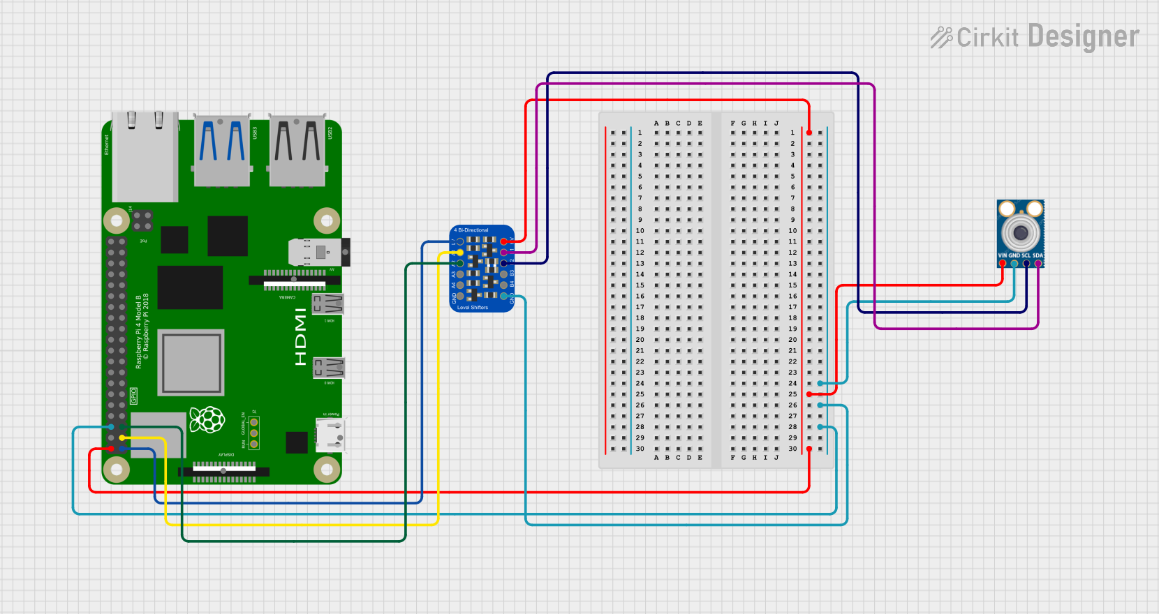
Pin Configuration and Descriptions

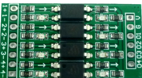
4-Channel Logic Level Converter

Pin Name Description
1 HV High Voltage (e.g., 5V)
2 LV Low Voltage (e.g., 3.3V)
3 GND Ground
4 HV1 High Voltage Channel 1
5 LV1 Low Voltage Channel 1
6 HV2 High Voltage Channel 2
7 LV2 Low Voltage Channel 2
8 HV3 High Voltage Channel 3
9 LV3 Low Voltage Channel 3
10 HV4 High Voltage Channel 4
11 LV4 Low Voltage Channel 4

Usage Instructions

How to Use the Component in a Circuit

  1. Power Connections:

    • Connect the HV pin to the high voltage supply (e.g., 5V).
    • Connect the LV pin to the low voltage supply (e.g., 3.3V).
    • Connect the GND pin to the ground of the circuit.
  2. Signal Connections:

    • Connect the high voltage signal to the corresponding HVx pin.
    • Connect the low voltage signal to the corresponding LVx pin.

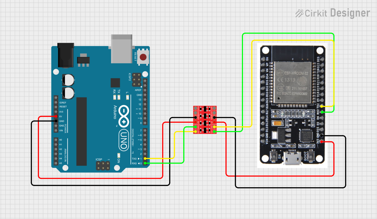
Example Circuit with Arduino UNO

**Components Needed:**
- Arduino UNO (5V logic)
- 3.3V sensor (e.g., BMP180)
- Logic Level Converter
- Jumper wires
- Breadboard

**Connections:**
1. Connect `HV` to Arduino 5V.
2. Connect `LV` to sensor 3.3V.
3. Connect `GND` to common ground.
4. Connect `HV1` to Arduino SDA (A4).
5. Connect `LV1` to sensor SDA.
6. Connect `HV2` to Arduino SCL (A5).
7. Connect `LV2` to sensor SCL.

Important Considerations and Best Practices

  • Voltage Matching: Ensure that the HV and LV pins are connected to the correct voltage levels.
  • Common Ground: Always connect the ground of the logic level converter to the ground of the circuit.
  • Current Limitation: Do not exceed the maximum current rating of 150mA per channel.
  • Bidirectional Use: The converter can handle bidirectional signals, making it suitable for I2C communication.

Troubleshooting and FAQs

Common Issues Users Might Face

  1. No Signal Conversion:

    • Solution: Check the power connections to HV and LV. Ensure they are connected to the correct voltage levels.
  2. Intermittent Communication:

    • Solution: Verify that the ground connections are secure and common across all components.
  3. Overheating:

    • Solution: Ensure that the current through each channel does not exceed 150mA. Check for short circuits.

FAQs

Q1: Can I use the logic level converter for analog signals?

  • A1: No, logic level converters are designed for digital signals only.

Q2: How many channels can I use simultaneously?

  • A2: You can use all available channels (4 or 8) simultaneously, provided you do not exceed the current rating.

Q3: Can I use the converter with a 1.8V device?

  • A3: Yes, the converter supports voltage levels as low as 1.8V.

Example Code for Arduino UNO

#include <Wire.h>
#include <Adafruit_BMP085.h>

Adafruit_BMP085 bmp;

void setup() {
  Serial.begin(9600);
  Wire.begin(); // Initialize I2C communication
  if (!bmp.begin()) {
    Serial.println("Could not find a valid BMP085 sensor, check wiring!");
    while (1) {}
  }
}

void loop() {
  Serial.print("Temperature = ");
  Serial.print(bmp.readTemperature());
  Serial.println(" *C");

  Serial.print("Pressure = ");
  Serial.print(bmp.readPressure());
  Serial.println(" Pa");

  delay(2000); // Wait for 2 seconds before next reading
}

This code initializes the BMP085 sensor and reads temperature and pressure values, displaying them on the serial monitor. Ensure the sensor is connected through the logic level converter as described in the example circuit.


This documentation provides a comprehensive guide to understanding, using, and troubleshooting a logic level converter. Whether you are a beginner or an experienced user, this guide aims to help you integrate this component effectively into your projects.