How to Use Custom OLED: Examples, Pinouts, and Specs
Introduction
The Custom OLED is a high-resolution organic light-emitting diode display designed to deliver vibrant colors and exceptional visual clarity. Its low power consumption and compact form factor make it ideal for portable devices, wearables, and applications requiring flexible display options. The Custom OLED is widely used in consumer electronics, IoT devices, and embedded systems where high-quality visuals are essential.
Explore Projects Built with Custom OLED


Explore Projects Built with Custom OLED
Common Applications:
- Smartwatches and fitness trackers
- Portable medical devices
- IoT dashboards and control panels
- Consumer electronics (e.g., MP3 players, cameras)
- Prototyping with microcontrollers like Arduino and Raspberry Pi
Technical Specifications
Below are the key technical details of the Custom OLED display:
| Parameter | Specification |
|---|---|
| Display Type | OLED (Organic Light-Emitting Diode) |
| Resolution | 128 x 64 pixels |
| Color Depth | Monochrome or RGB (depending on model) |
| Operating Voltage | 3.3V to 5V |
| Interface | I2C or SPI |
| Power Consumption | < 20mW (typical) |
| Viewing Angle | ~160° |
| Operating Temperature | -40°C to +85°C |
| Dimensions | 1.3" diagonal (customizable sizes) |
Pin Configuration
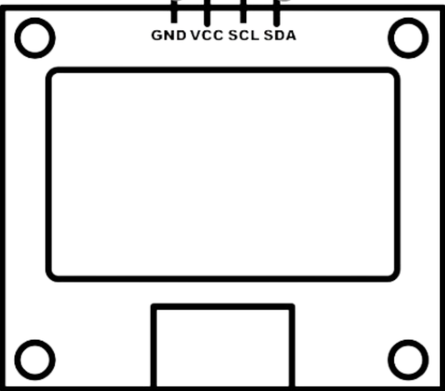
The Custom OLED typically comes with a 4-pin or 7-pin interface, depending on the communication protocol (I2C or SPI). Below is the pin configuration for both modes:
I2C Mode Pinout:
| Pin | Name | Description |
|---|---|---|
| 1 | GND | Ground (0V reference) |
| 2 | VCC | Power supply (3.3V or 5V) |
| 3 | SCL | Serial Clock Line (I2C clock) |
| 4 | SDA | Serial Data Line (I2C data) |
SPI Mode Pinout:
| Pin | Name | Description |
|---|---|---|
| 1 | GND | Ground (0V reference) |
| 2 | VCC | Power supply (3.3V or 5V) |
| 3 | SCK | Serial Clock (SPI clock) |
| 4 | MOSI | Master Out Slave In (SPI data) |
| 5 | RES | Reset pin |
| 6 | DC | Data/Command control pin |
| 7 | CS | Chip Select |
Usage Instructions
Connecting the Custom OLED to an Arduino UNO
The Custom OLED can be easily interfaced with an Arduino UNO using the I2C protocol. Follow these steps to set up the display:
Wiring:
- Connect the
GNDpin of the OLED to theGNDpin on the Arduino. - Connect the
VCCpin of the OLED to the5Vpin on the Arduino. - Connect the
SCLpin of the OLED to theA5pin on the Arduino (I2C clock). - Connect the
SDApin of the OLED to theA4pin on the Arduino (I2C data).
- Connect the
Install Required Libraries:
- Download and install the
Adafruit_GFXandAdafruit_SSD1306libraries from the Arduino Library Manager.
- Download and install the
Example Code: Use the following code to display text on the Custom OLED:
// Include necessary libraries
#include <Wire.h>
#include <Adafruit_GFX.h>
#include <Adafruit_SSD1306.h>

// Define OLED display width and height
#define SCREEN_WIDTH 128
#define SCREEN_HEIGHT 64

// Create an instance of the display object
Adafruit_SSD1306 display(SCREEN_WIDTH, SCREEN_HEIGHT, &Wire, -1);

void setup() {
  // Initialize the display
  if (!display.begin(SSD1306_I2C_ADDRESS, 0x3C)) {
    // Display initialization failed
    Serial.println(F("SSD1306 allocation failed"));
    for (;;); // Halt execution
  }

  // Clear the display buffer
  display.clearDisplay();

  // Set text size and color
  display.setTextSize(1); // Normal 1:1 pixel scale
  display.setTextColor(SSD1306_WHITE);

  // Display a message
  display.setCursor(0, 0); // Start at top-left corner
  display.println(F("Hello, Custom OLED!"));
  display.display(); // Render the text
}

void loop() {
  // Nothing to do here
}
Important Considerations:
- Ensure the OLED's operating voltage matches your microcontroller's logic level (3.3V or 5V).
- Use pull-up resistors (4.7kΩ to 10kΩ) on the I2C lines (SCL and SDA) if not already included on the OLED module.
- Avoid exposing the OLED to direct sunlight for extended periods, as it may degrade the display.
Troubleshooting and FAQs
Common Issues and Solutions:
The display does not turn on:
- Verify the wiring connections and ensure the power supply is stable.
- Check if the I2C address (default:
0x3C) matches the one in your code.
Text or graphics are not displayed correctly:
- Ensure the correct resolution (128x64) is defined in the code.
- Confirm that the appropriate libraries (
Adafruit_GFXandAdafruit_SSD1306) are installed and up to date.
Flickering or unstable display:
- Check for loose connections or poor soldering on the pins.
- Use a decoupling capacitor (e.g., 0.1µF) across the power supply pins to reduce noise.
The display is too dim:
- Verify the power supply voltage is within the specified range.
- Adjust the contrast settings in the library if supported.
FAQs:
Q: Can I use the Custom OLED with a Raspberry Pi?
A: Yes, the Custom OLED is compatible with Raspberry Pi via I2C or SPI. Use the appropriate libraries likeluma.oledfor Python.Q: How do I change the I2C address of the OLED?
A: Some OLED modules have solder jumpers on the back to modify the I2C address. Refer to the module's datasheet for details.Q: Can the Custom OLED display images?
A: Yes, you can display images by converting them into a bitmap format and using theAdafruit_GFXlibrary to render them.
By following this documentation, you can effectively integrate the Custom OLED into your projects and troubleshoot common issues with ease.