How to Use NodeMCU V3 ESP8266: Examples, Pinouts, and Specs
Introduction
The NodeMCU V3 ESP8266 is a versatile development board that integrates the ESP8266 Wi-Fi module with a microcontroller. This board is widely used in the realm of Internet of Things (IoT) for creating projects that require wireless communication capabilities. It is suitable for hobbyists, educators, and professionals looking to develop connected devices with ease.
Explore Projects Built with NodeMCU V3 ESP8266
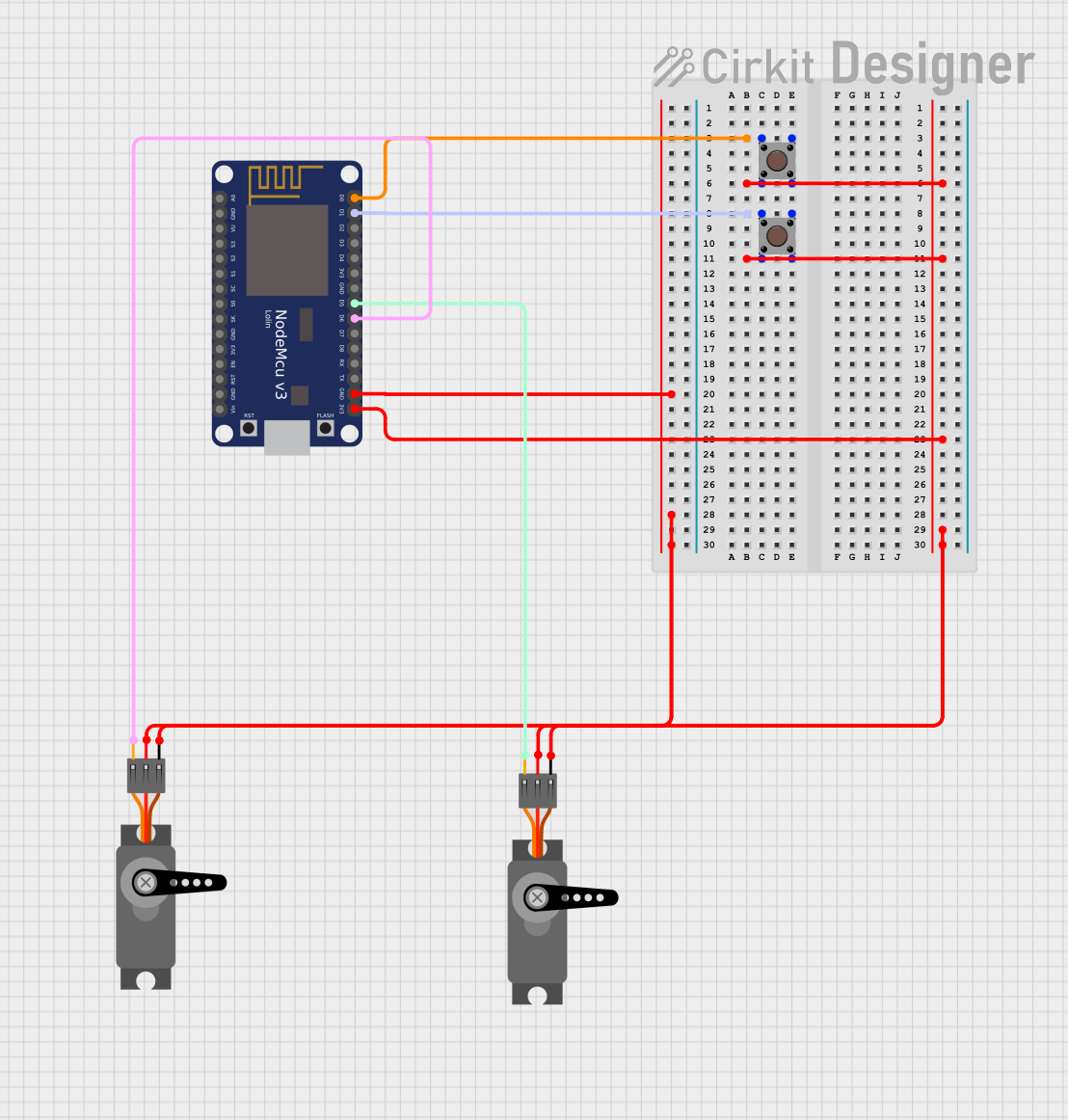
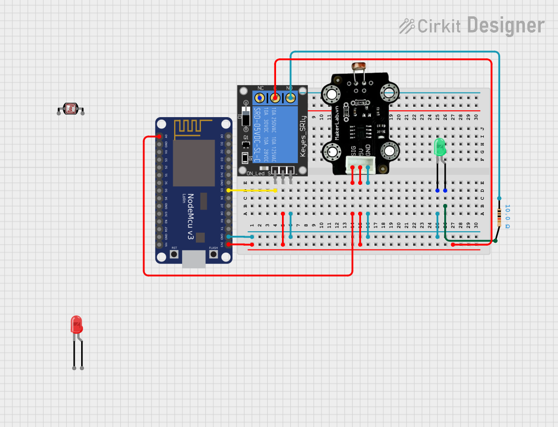
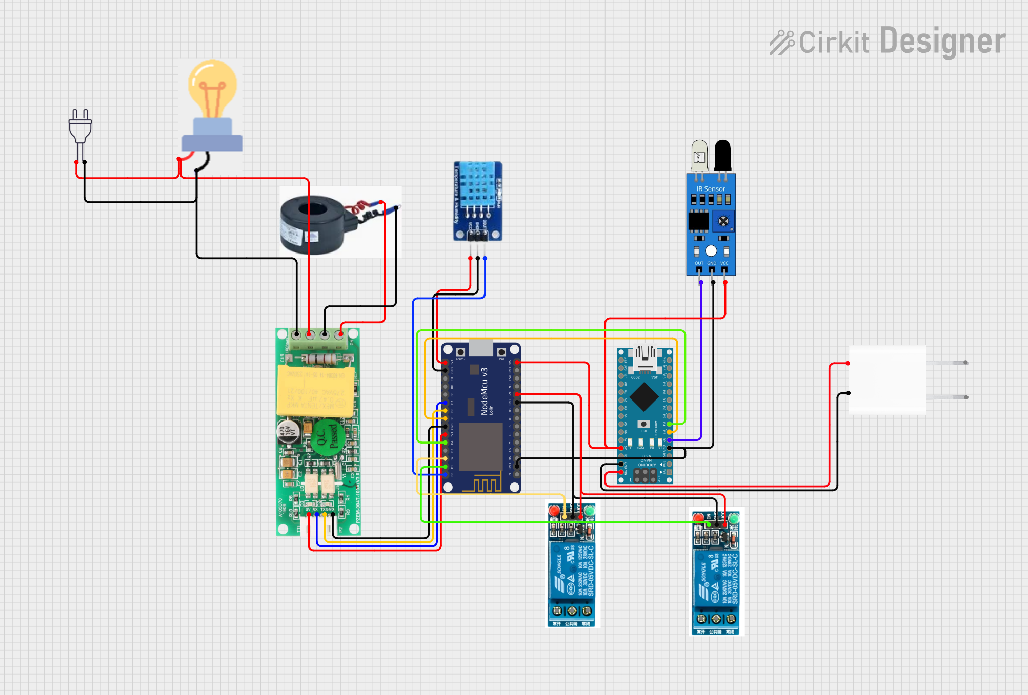

Explore Projects Built with NodeMCU V3 ESP8266
Common Applications and Use Cases
- Smart home devices
- Wireless sensors
- IoT prototypes
- Remote control applications
- Data logging
Technical Specifications
Key Technical Details
- Operating Voltage: 3.3V
- Digital I/O Pins: 11 (all pins have interrupt/pwm/I2C/one-wire support except D0)
- Analog Input Pins: 1 (A0)
- Flash Memory: 4MB
- Wi-Fi Protocol: 802.11 b/g/n
- Wi-Fi Mode: AP (Access Point), STA (Standalone), AP+STA
- Serial Communication: UART, SPI, I2C
- Clock Speed: 80MHz (default), up to 160MHz
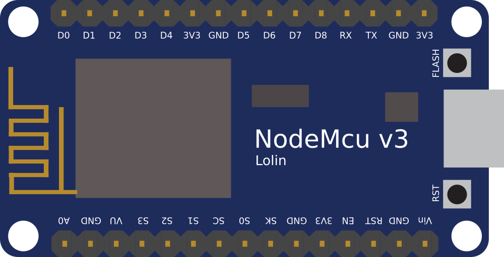
Pin Configuration and Descriptions
| Pin | Function | Description |
|---|---|---|
| GND | Ground | Reference ground for power and logic |
| 3V3 | 3.3V Power | Power supply for the board (3.3V input) |
| VIN | Voltage Input | 5V input from USB or battery |
| RST | Reset | Resets the module (active low) |
| EN | Chip Enable | Enables the chip (active high) |
| D0-D10 | GPIO | General Purpose Input/Output pins |
| A0 | Analog Input | Analog input, max 3.3V input |
| SDx | SPI Data | SPI communication pins |
| SCx | SPI Clock | SPI clock pin |
| TX | Transmit | UART transmit pin |
| RX | Receive | UART receive pin |
Usage Instructions
How to Use the Component in a Circuit
- Powering the NodeMCU: Connect the VIN pin to a 5V supply if using USB or battery, or provide 3.3V directly to the 3V3 pin.
- Connecting to Wi-Fi: Utilize the ESP8266's Wi-Fi capabilities to connect to a network for IoT applications.
- Programming the NodeMCU: Use the Arduino IDE or other compatible software to write and upload code to the board via the micro-USB port.
- Interfacing with Sensors/Actuators: Connect sensors to the GPIO pins and read/write data to interact with the physical world.
Important Considerations and Best Practices
- Always ensure that the power supply is within the specified range to prevent damage.
- Use a logic level converter if interfacing with components that operate at 5V logic levels.
- Avoid drawing too much current from the GPIO pins to prevent damage (max 12mA per pin).
- Ensure proper decoupling with capacitors near the power pins to maintain a stable power supply.
Example Code for Arduino UNO
// Basic example to connect NodeMCU to Wi-Fi

#include <ESP8266WiFi.h>

const char* ssid = "yourSSID"; // Replace with your Wi-Fi SSID
const char* password = "yourPASSWORD"; // Replace with your Wi-Fi password

void setup() {
  Serial.begin(115200); // Start serial communication at 115200 baud
  WiFi.begin(ssid, password); // Start Wi-Fi connection with SSID and password

  while (WiFi.status() != WL_CONNECTED) {
    delay(500);
    Serial.print(".");
  }

  Serial.println("");
  Serial.println("Wi-Fi connected");
  Serial.println("IP address: ");
  Serial.println(WiFi.localIP()); // Print the local IP address
}

void loop() {
  // User code to run repeatedly
}
Troubleshooting and FAQs
Common Issues Users Might Face
- NodeMCU not connecting to Wi-Fi: Ensure the SSID and password are correct. Check the signal strength and router settings.
- NodeMCU not recognized by computer: Verify the USB cable and drivers are correct. Try different USB ports or cables.
- GPIO pin not working: Check for proper pin initialization in the code and ensure there is no physical damage to the board.
Solutions and Tips for Troubleshooting
- Power issues: Use a stable power source. If using USB, ensure the computer port provides sufficient power.
- Firmware issues: Reflash the NodeMCU with the correct firmware if there are issues with the current installation.
- Code problems: Verify the code for errors, check the baud rate, and ensure proper libraries are included.
FAQs
Q: Can the NodeMCU be powered by a 5V supply? A: Yes, via the VIN pin when using USB or an external battery.
Q: How many digital I/O pins does the NodeMCU have? A: The NodeMCU V3 has 11 digital I/O pins.
Q: What is the maximum analog voltage that can be read on the A0 pin? A: The maximum voltage is 3.3V for the A0 pin.
Q: Can the NodeMCU be programmed with Arduino IDE? A: Yes, the NodeMCU is compatible with the Arduino IDE. Make sure to install the ESP8266 board package.
Q: What should I do if the NodeMCU is not connecting to Wi-Fi? A: Check your SSID and password, ensure the Wi-Fi network is operational, and verify the signal strength. If the issue persists, consider checking your code and resetting the NodeMCU.