
How to Use 400V Step Up Module: Examples, Pinouts, and Specs
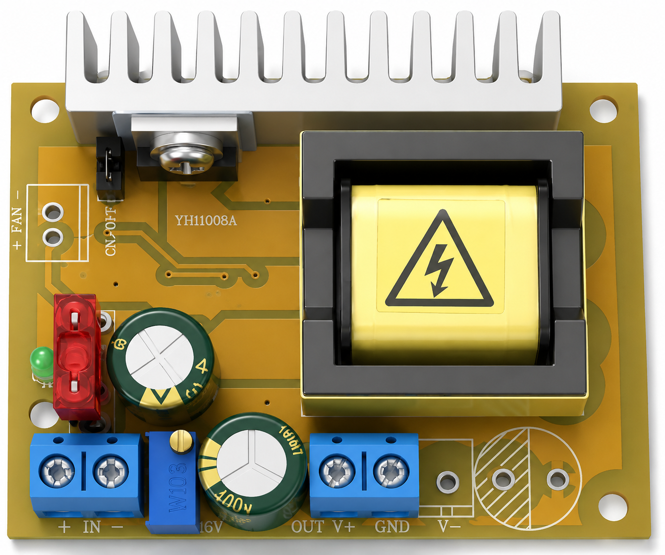
 Design with 400V Step Up Module in Cirkit Designer
Introduction
The 400V Step Up Module is an electronic device designed to increase a lower input voltage to a stable 400V output. This module is commonly used in applications requiring high voltage for efficient power transmission, powering high-voltage equipment, or driving devices such as Nixie tubes, Geiger counters, or other specialized circuits. Its compact design and high efficiency make it a popular choice for hobbyists, engineers, and professionals working with high-voltage systems.
Explore Projects Built with 400V Step Up Module
 Open Project in Cirkit Designer
 Open Project in Cirkit Designer
 Open Project in Cirkit Designer
 Open Project in Cirkit Designer
Explore Projects Built with 400V Step Up Module
Open Project in Cirkit DesignerOpen Project in Cirkit DesignerOpen Project in Cirkit DesignerOpen Project in Cirkit DesignerCommon Applications:
- Powering Nixie tubes and vacuum fluorescent displays (VFDs)
- Geiger counters and radiation detection systems
- High-voltage testing equipment
- Scientific experiments requiring high-voltage sources
- DIY electronics projects involving high-voltage circuits
Technical Specifications
Below are the key technical details of the 400V Step Up Module:
| Parameter | Value |
|---|---|
| Input Voltage Range | 3V to 12V DC |
| Output Voltage | 400V DC (fixed) |
| Output Current | 1mA to 2mA (depending on load) |
| Efficiency | Up to 85% |
| Dimensions | Typically 30mm x 20mm x 10mm |
| Operating Temperature | -20°C to +60°C |
| Protection Features | Overcurrent and short-circuit protection |
Pin Configuration and Descriptions
The module typically has four pins or solder pads for connections:
| Pin Name | Description |
|---|---|
| VIN+ | Positive input voltage (3V to 12V DC) |
| VIN- | Negative input voltage (ground) |
| VOUT+ | Positive high-voltage output (400V DC) |
| VOUT- | Negative high-voltage output (ground) |
Usage Instructions
How to Use the 400V Step Up Module in a Circuit
- Power Supply: Connect a DC power source (3V to 12V) to the
VIN+andVIN-pins. Ensure the input voltage is within the specified range to avoid damaging the module. - Load Connection: Connect the high-voltage load (e.g., Nixie tube or Geiger counter) to the
VOUT+andVOUT-pins. Ensure the load is designed to handle 400V DC. - Testing: Use a multimeter with a high-voltage probe to verify the output voltage before connecting sensitive components.
- Mounting: Secure the module on a non-conductive surface to prevent accidental short circuits or arcing.
Important Considerations and Best Practices
- Safety First: The 400V output is dangerous and can cause serious injury. Always handle the module with care and avoid touching exposed connections while powered.
- Load Compatibility: Ensure the connected load is designed to operate at 400V DC and does not exceed the module's current rating.
- Heat Dissipation: Although the module is efficient, prolonged use at high loads may generate heat. Ensure adequate ventilation or use a heatsink if necessary.
- Isolation: Avoid direct contact with the high-voltage output. Use proper insulation and isolation techniques in your circuit design.
- Arduino Integration: While the module itself does not directly interface with microcontrollers, it can be used in Arduino projects to power high-voltage components like Nixie tubes. Below is an example of controlling a Nixie tube powered by the 400V Step Up Module.
Example Arduino Code for Nixie Tube Control
// Example code to control a Nixie tube using an Arduino UNO
// Ensure the 400V Step Up Module is properly connected to the Nixie tube
// and the Arduino controls the tube via a transistor or driver circuit.

const int nixieControlPin = 7; // Pin connected to the Nixie tube driver circuit

void setup() {
  pinMode(nixieControlPin, OUTPUT); // Set the control pin as an output
}

void loop() {
  digitalWrite(nixieControlPin, HIGH); // Turn on the Nixie tube
  delay(1000); // Keep it on for 1 second
  digitalWrite(nixieControlPin, LOW);  // Turn off the Nixie tube
  delay(1000); // Keep it off for 1 second
}
Note: The Arduino does not directly control the 400V output. Instead, it switches the Nixie tube on/off via a transistor or driver circuit. Ensure proper isolation between the Arduino and high-voltage components.
Troubleshooting and FAQs
Common Issues and Solutions
No Output Voltage:
- Cause: Insufficient input voltage or loose connections.
- Solution: Verify the input voltage is within the 3V to 12V range and check all connections.
Output Voltage Too Low:
- Cause: Excessive load or input voltage too low.
- Solution: Reduce the load or increase the input voltage within the specified range.
Module Overheating:
- Cause: Prolonged operation at maximum load or poor ventilation.
- Solution: Improve ventilation or reduce the load.
Arcing or Sparks:
- Cause: Poor insulation or exposed high-voltage connections.
- Solution: Ensure all high-voltage connections are properly insulated and spaced apart.
FAQs
Q: Can I adjust the output voltage?
A: No, the output voltage is fixed at 400V DC and cannot be adjusted.Q: Is the module safe for beginners?
A: While it can be used by beginners, caution is required due to the high voltage. Always follow safety guidelines.Q: Can I use this module with an Arduino?
A: Yes, but the Arduino does not directly interact with the high-voltage output. Use a driver circuit to control high-voltage components like Nixie tubes.Q: What happens if I exceed the input voltage range?
A: Exceeding the input voltage range may damage the module permanently. Always use a regulated power supply.
By following this documentation, you can safely and effectively use the 400V Step Up Module in your high-voltage projects.