How to Use raspberry pi pinout: Examples, Pinouts, and Specs
Introduction
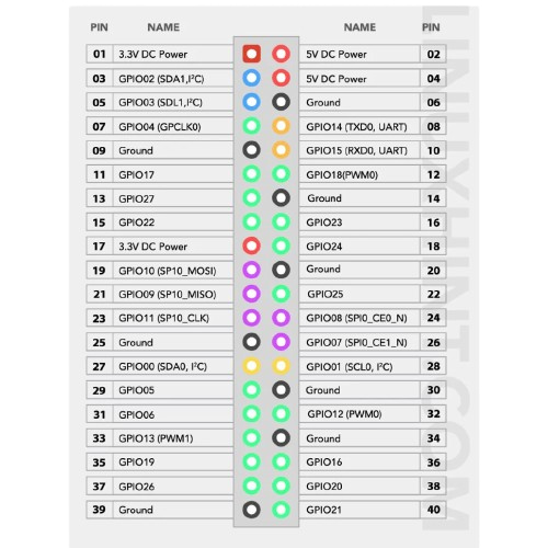
The Raspberry Pi Pinout is a detailed diagram that illustrates the arrangement and functionality of the GPIO (General Purpose Input/Output) pins on a Raspberry Pi board. Manufactured by RPPO (Part ID: RPPO), this pinout provides essential information about the power, ground, and communication protocol pins available on the Raspberry Pi. It is an indispensable reference for developers, hobbyists, and engineers working on Raspberry Pi-based projects.
Explore Projects Built with raspberry pi pinout
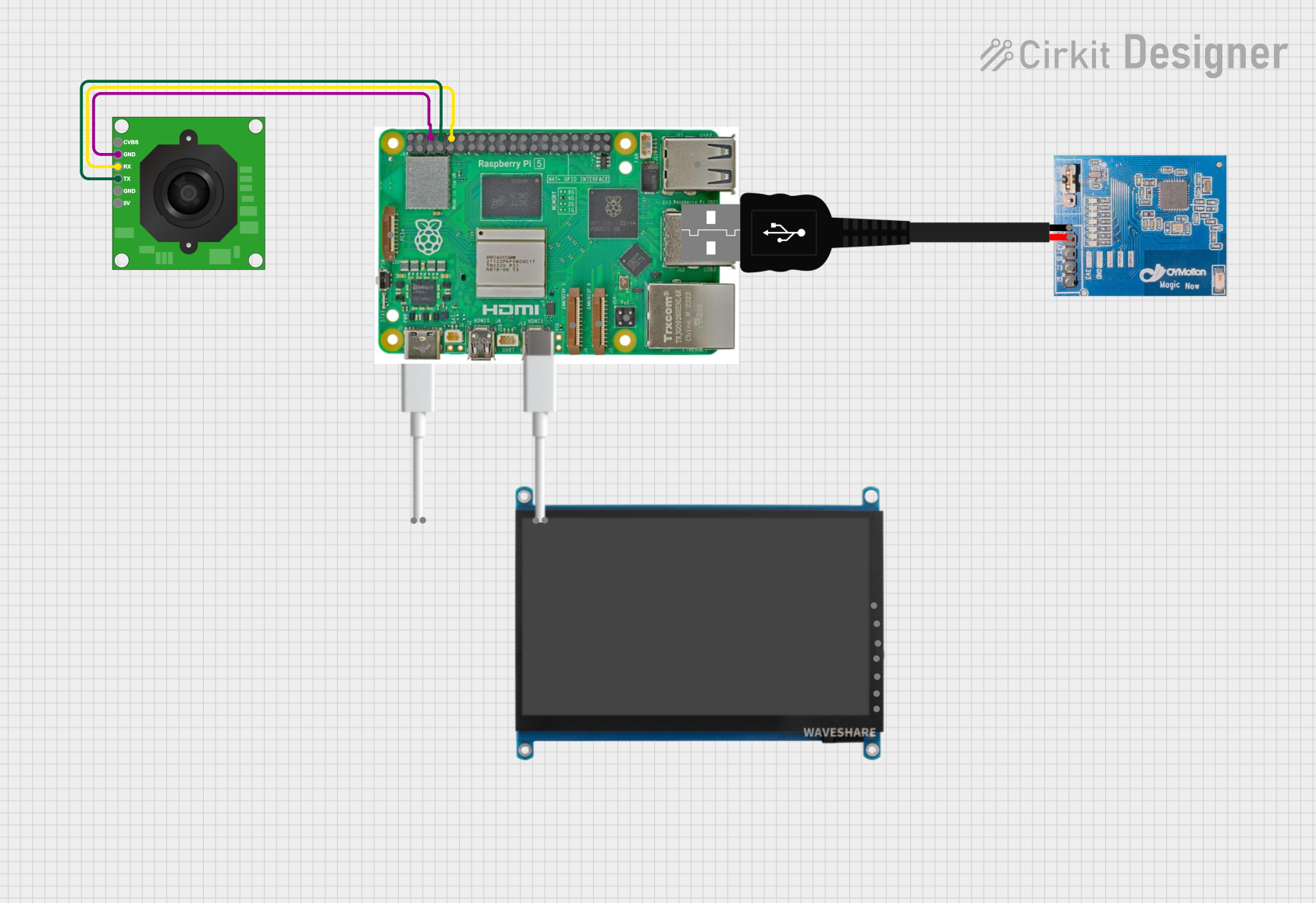
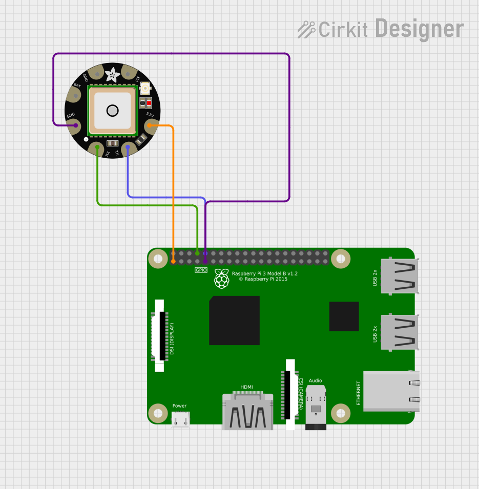
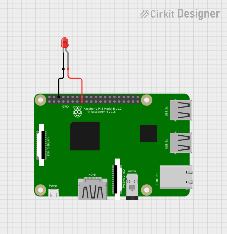

Explore Projects Built with raspberry pi pinout
Common Applications and Use Cases
- Connecting sensors, actuators, and other peripherals to the Raspberry Pi.
- Prototyping IoT (Internet of Things) devices.
- Building robotics and automation systems.
- Interfacing with communication protocols like I2C, SPI, and UART.
- Powering external devices or modules.
Technical Specifications
The Raspberry Pi GPIO header typically consists of 40 pins (on most modern Raspberry Pi models). These pins are divided into power, ground, and GPIO pins, with some dedicated to specific communication protocols. Below are the key technical details:
Key Technical Details
- Voltage Levels: 3.3V logic level (GPIO pins are not 5V tolerant).
- Power Pins: 5V and 3.3V power output pins.
- Ground Pins: Multiple ground (GND) pins for circuit grounding.
- Communication Protocols: I2C, SPI, UART.
- Maximum Current: 16mA per GPIO pin, with a total maximum of 50mA across all GPIO pins.
Pin Configuration and Descriptions
The following table provides a detailed description of the 40-pin GPIO header:
| Pin Number | Pin Name | Function/Description |
|---|---|---|
| 1 | 3.3V Power | 3.3V power output |
| 2 | 5V Power | 5V power output |
| 3 | GPIO2 (SDA1) | I2C Data (SDA) |
| 4 | 5V Power | 5V power output |
| 5 | GPIO3 (SCL1) | I2C Clock (SCL) |
| 6 | GND | Ground |
| 7 | GPIO4 | General-purpose GPIO |
| 8 | GPIO14 (TXD) | UART Transmit (TX) |
| 9 | GND | Ground |
| 10 | GPIO15 (RXD) | UART Receive (RX) |
| 11 | GPIO17 | General-purpose GPIO |
| 12 | GPIO18 (PWM0) | PWM output |
| 13 | GPIO27 | General-purpose GPIO |
| 14 | GND | Ground |
| 15 | GPIO22 | General-purpose GPIO |
| 16 | GPIO23 | General-purpose GPIO |
| 17 | 3.3V Power | 3.3V power output |
| 18 | GPIO24 | General-purpose GPIO |
| 19 | GPIO10 (MOSI) | SPI Master Out Slave In (MOSI) |
| 20 | GND | Ground |
| 21 | GPIO9 (MISO) | SPI Master In Slave Out (MISO) |
| 22 | GPIO25 | General-purpose GPIO |
| 23 | GPIO11 (SCLK) | SPI Clock (SCLK) |
| 24 | GPIO8 (CE0) | SPI Chip Enable 0 (CE0) |
| 25 | GND | Ground |
| 26 | GPIO7 (CE1) | SPI Chip Enable 1 (CE1) |
| 27 | GPIO0 (ID_SD) | I2C ID EEPROM Data |
| 28 | GPIO1 (ID_SC) | I2C ID EEPROM Clock |
| 29 | GPIO5 | General-purpose GPIO |
| 30 | GND | Ground |
| 31 | GPIO6 | General-purpose GPIO |
| 32 | GPIO12 (PWM0) | PWM output |
| 33 | GPIO13 (PWM1) | PWM output |
| 34 | GND | Ground |
| 35 | GPIO19 (MISO) | SPI Master In Slave Out (MISO) |
| 36 | GPIO16 | General-purpose GPIO |
| 37 | GPIO26 | General-purpose GPIO |
| 38 | GPIO20 (MOSI) | SPI Master Out Slave In (MOSI) |
| 39 | GND | Ground |
| 40 | GPIO21 (SCLK) | SPI Clock (SCLK) |
Usage Instructions
How to Use the Raspberry Pi Pinout in a Circuit
- Identify the Pinout: Refer to the pinout diagram to locate the required pins for your project.
- Connect Power and Ground: Use the 5V or 3.3V power pins to power external devices, and connect the GND pins to establish a common ground.
- Interface with GPIO Pins: Connect sensors, actuators, or other peripherals to the GPIO pins. Ensure the voltage levels are compatible (3.3V logic).
- Use Communication Protocols: For I2C, SPI, or UART communication, connect the appropriate pins (e.g., SDA/SCL for I2C).
- Enable GPIO in Software: Use libraries like
RPi.GPIOorgpiozeroin Python to control the GPIO pins programmatically.
Important Considerations and Best Practices
- Voltage Compatibility: Do not apply 5V to GPIO pins, as they operate at 3.3V logic levels.
- Current Limits: Avoid exceeding the maximum current rating (16mA per pin, 50mA total).
- Use Resistors: Add pull-up or pull-down resistors as needed to stabilize input signals.
- Avoid Short Circuits: Double-check connections to prevent damage to the Raspberry Pi.
Example Code for GPIO Control with Arduino UNO
If you are interfacing the Raspberry Pi with an Arduino UNO, you can use the following example code to send data from the Arduino to the Raspberry Pi via UART:
// Arduino UNO Code: Send data to Raspberry Pi via UART
void setup() {
  Serial.begin(9600); // Initialize UART communication at 9600 baud
}

void loop() {
  Serial.println("Hello, Raspberry Pi!"); // Send a message to the Raspberry Pi
  delay(1000); // Wait for 1 second before sending the next message
}
On the Raspberry Pi, you can use the following Python code to receive the data:
Raspberry Pi Code: Receive data from Arduino via UART
import serial
Initialize UART communication (adjust port and baud rate as needed)
ser = serial.Serial('/dev/ttyS0', 9600)
while True: if ser.in_waiting > 0: # Check if data is available data = ser.readline().decode('utf-8').strip() # Read and decode data print(f"Received: {data}") # Print the received message
Troubleshooting and FAQs
Common Issues and Solutions
GPIO Pins Not Responding
- Cause: GPIO pins may not be enabled in the Raspberry Pi configuration.
- Solution: Run
sudo raspi-configand enable GPIO under the "Interfacing Options."
Incorrect Voltage Levels
- Cause: Connecting 5V devices directly to GPIO pins.
- Solution: Use a logic level shifter to safely interface 5V devices with 3.3V GPIO pins.
Communication Protocol Not Working
- Cause: Incorrect pin connections or software configuration.
- Solution: Double-check the pin connections and ensure the correct protocol is enabled in the Raspberry Pi settings.
Overheating or Damage
- Cause: Exceeding current limits or short circuits.
- Solution: Use current-limiting resistors and verify connections before powering the circuit.
FAQs
Q: Can I power the Raspberry Pi through the GPIO pins?
- A: Yes, you can power the Raspberry Pi by supplying 5V to the 5V pin and connecting GND. However, this bypasses the onboard voltage regulation and protection circuits, so proceed with caution.
Q: How do I identify the GPIO pin numbers?
- A: Use the
pinoutcommand in the Raspberry Pi terminal to display a detailed pinout diagram.
- A: Use the
Q: Can I use multiple communication protocols simultaneously?
- A: Yes, the Raspberry Pi supports simultaneous use of I2C, SPI, and UART, provided the pins are not shared between devices.
This documentation provides a comprehensive guide to understanding and using the Raspberry Pi Pinout effectively. For further assistance, refer to the official Raspberry Pi documentation or community forums.