Cirkit Designer Logo
Cirkit Designer
Your all-in-one circuit design IDE
Home / 
Component Documentation

How to Use A4988 Stepper Driver: Examples, Pinouts, and Specs

Image of A4988 Stepper Driver
Cirkit Designer LogoDesign with A4988 Stepper Driver in Cirkit Designer

Introduction

The A4988 is a microstepping driver designed for controlling bipolar stepper motors. It enables precise control of motor position and speed, making it ideal for applications requiring high accuracy and smooth motion. The driver features adjustable current control, over-temperature protection, and a straightforward interface, making it easy to integrate into a wide range of projects.

Explore Projects Built with A4988 Stepper Driver

Use Cirkit Designer to design, explore, and prototype these projects online. Some projects support real-time simulation. Click "Open Project" to start designing instantly!
A4988 Stepper Motor Driver Controlled Bipolar Stepper Motor
Image of idk: A project utilizing A4988 Stepper Driver in a practical application
This circuit is designed to control a bipolar stepper motor using an A4988 stepper motor driver. The driver interfaces with the motor by connecting its output pins to the motor's coils, allowing precise control of the motor's movement.
Cirkit Designer LogoOpen Project in Cirkit Designer
Arduino Mega 2560-Controlled Stepper Motors with RFID Access and Traffic Light Indication
Image of Copy of test: A project utilizing A4988 Stepper Driver in a practical application
This circuit controls two 28BYJ-48 stepper motors using A4988 stepper motor driver carriers, interfaced with an Arduino Mega 2560 microcontroller. It features an RFID-RC522 module for RFID reading, a 16x4 LCD display with I2C interface for user interaction, and a piezo speaker for audio feedback. Additionally, there is a traffic light module controlled by the Arduino, and a 48V to 5V converter to step down voltage for the logic levels. The power supply provides 12V to the motor drivers and is connected to a standard power outlet.
Cirkit Designer LogoOpen Project in Cirkit Designer
RFID-Activated Traffic Light Controller with Auditory Feedback Using Arduino Mega
Image of test: A project utilizing A4988 Stepper Driver in a practical application
This circuit is designed to control two 28BYJ-48 stepper motors using A4988 stepper motor driver carriers, with an Arduino Mega 2560 as the central microcontroller. It includes an RFID-RC522 module for RFID reading, an LCD display for user interface, and a traffic light and piezo speaker for visual and audio signaling. The circuit is powered by a 12V 5A power supply, which is stepped down to 5V for logic level components, and it interfaces with a power outlet for AC to DC conversion.
Cirkit Designer LogoOpen Project in Cirkit Designer
Teensy-Controlled Stepper Motor and Servo Actuation System
Image of Prototype Robotic Arm: A project utilizing A4988 Stepper Driver in a practical application
This circuit controls a bipolar stepper motor using an A4988 Stepper Motor Driver, which is interfaced with a Teensy 4.1 microcontroller. The Teensy sends step and direction signals to the driver, while the driver's RESET and SLEEP pins are tied together, likely for simplified control. Additionally, the circuit includes an Adafruit PCA9685 PWM Servo Breakout board, which is connected to a servo motor and communicates with the Teensy via I2C, and both the driver and the breakout board are powered by separate power supplies with decoupling provided by an electrolytic capacitor.
Cirkit Designer LogoOpen Project in Cirkit Designer

Explore Projects Built with A4988 Stepper Driver

Use Cirkit Designer to design, explore, and prototype these projects online. Some projects support real-time simulation. Click "Open Project" to start designing instantly!
Image of idk: A project utilizing A4988 Stepper Driver in a practical application
A4988 Stepper Motor Driver Controlled Bipolar Stepper Motor
This circuit is designed to control a bipolar stepper motor using an A4988 stepper motor driver. The driver interfaces with the motor by connecting its output pins to the motor's coils, allowing precise control of the motor's movement.
Cirkit Designer LogoOpen Project in Cirkit Designer
Image of Copy of test: A project utilizing A4988 Stepper Driver in a practical application
Arduino Mega 2560-Controlled Stepper Motors with RFID Access and Traffic Light Indication
This circuit controls two 28BYJ-48 stepper motors using A4988 stepper motor driver carriers, interfaced with an Arduino Mega 2560 microcontroller. It features an RFID-RC522 module for RFID reading, a 16x4 LCD display with I2C interface for user interaction, and a piezo speaker for audio feedback. Additionally, there is a traffic light module controlled by the Arduino, and a 48V to 5V converter to step down voltage for the logic levels. The power supply provides 12V to the motor drivers and is connected to a standard power outlet.
Cirkit Designer LogoOpen Project in Cirkit Designer
Image of test: A project utilizing A4988 Stepper Driver in a practical application
RFID-Activated Traffic Light Controller with Auditory Feedback Using Arduino Mega
This circuit is designed to control two 28BYJ-48 stepper motors using A4988 stepper motor driver carriers, with an Arduino Mega 2560 as the central microcontroller. It includes an RFID-RC522 module for RFID reading, an LCD display for user interface, and a traffic light and piezo speaker for visual and audio signaling. The circuit is powered by a 12V 5A power supply, which is stepped down to 5V for logic level components, and it interfaces with a power outlet for AC to DC conversion.
Cirkit Designer LogoOpen Project in Cirkit Designer
Image of Prototype Robotic Arm: A project utilizing A4988 Stepper Driver in a practical application
Teensy-Controlled Stepper Motor and Servo Actuation System
This circuit controls a bipolar stepper motor using an A4988 Stepper Motor Driver, which is interfaced with a Teensy 4.1 microcontroller. The Teensy sends step and direction signals to the driver, while the driver's RESET and SLEEP pins are tied together, likely for simplified control. Additionally, the circuit includes an Adafruit PCA9685 PWM Servo Breakout board, which is connected to a servo motor and communicates with the Teensy via I2C, and both the driver and the breakout board are powered by separate power supplies with decoupling provided by an electrolytic capacitor.
Cirkit Designer LogoOpen Project in Cirkit Designer

Common Applications

  • 3D printers
  • CNC machines
  • Robotics
  • Automated systems
  • Camera sliders and gimbals

Technical Specifications

The A4988 stepper driver is a compact and versatile component with the following key specifications:

Parameter Value
Motor Type Supported Bipolar stepper motors
Operating Voltage 8 V to 35 V
Logic Voltage 3.3 V or 5 V
Maximum Output Current 2 A per coil (with sufficient cooling)
Microstepping Modes Full, 1/2, 1/4, 1/8, 1/16
Current Control Adjustable via potentiometer
Protection Features Over-temperature, short-circuit, under-voltage lockout

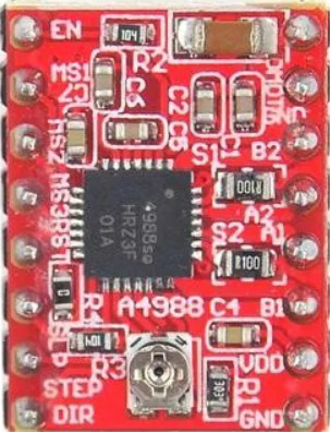
Pin Configuration and Descriptions

The A4988 has 16 pins, each serving a specific function. Below is the pinout and description:

Pin Name Pin Number Description
VMOT 1 Motor power supply (8 V to 35 V). Connect to the stepper motor power source.
GND 2, 3 Ground connection for motor and logic circuits.
VDD 4 Logic voltage supply (3.3 V or 5 V).
STEP 5 Step input. A rising edge on this pin advances the motor one step.
DIR 6 Direction input. High or low determines the motor's rotation direction.
ENABLE 7 Enable input. Low to enable the driver, high to disable it.
MS1, MS2, MS3 8, 9, 10 Microstepping resolution selection pins.
RESET 11 Resets the internal logic. Active low.
SLEEP 12 Puts the driver into low-power sleep mode. Active low.
OUT1A, OUT1B 13, 14 Outputs for one motor coil. Connect to one coil of the stepper motor.
OUT2A, OUT2B 15, 16 Outputs for the other motor coil. Connect to the second coil of the stepper motor.

Usage Instructions

How to Use the A4988 in a Circuit

  1. Power Connections:

    • Connect the VMOT pin to the motor power supply (8 V to 35 V).
    • Connect the GND pins to the ground of both the motor and logic power supplies.
    • Connect the VDD pin to the logic power supply (3.3 V or 5 V).
  2. Motor Connections:

    • Connect the stepper motor coils to the OUT1A, OUT1B, OUT2A, and OUT2B pins. Ensure the correct pairing of the motor wires.
  3. Control Pins:

    • Use the STEP pin to control the motor's steps. Each rising edge moves the motor one step.
    • Use the DIR pin to set the motor's rotation direction.
    • Adjust the microstepping resolution using the MS1, MS2, and MS3 pins.
  4. Current Adjustment:

    • Use the onboard potentiometer to set the current limit. This prevents overheating and ensures optimal motor performance.
  5. Optional Features:

    • Use the ENABLE pin to enable or disable the driver.
    • Use the SLEEP pin to put the driver into low-power mode when not in use.

Example: Connecting the A4988 to an Arduino UNO

Below is an example of how to control a stepper motor using the A4988 and an Arduino UNO:

Circuit Diagram

  • Connect the A4988's STEP and DIR pins to Arduino digital pins 2 and 3, respectively.
  • Connect the ENABLE pin to ground to enable the driver.
  • Connect the motor power supply to VMOT and GND.
  • Connect the stepper motor coils to the OUT1A, OUT1B, OUT2A, and OUT2B pins.

Arduino Code

// Define pin connections
#define STEP_PIN 2  // Connect to A4988 STEP pin
#define DIR_PIN 3   // Connect to A4988 DIR pin

void setup() {
  pinMode(STEP_PIN, OUTPUT); // Set STEP pin as output
  pinMode(DIR_PIN, OUTPUT);  // Set DIR pin as output

  digitalWrite(DIR_PIN, HIGH); // Set initial direction (HIGH = clockwise)
}

void loop() {
  // Generate a step pulse
  digitalWrite(STEP_PIN, HIGH); // Set STEP pin HIGH
  delayMicroseconds(1000);      // Wait 1 ms
  digitalWrite(STEP_PIN, LOW);  // Set STEP pin LOW
  delayMicroseconds(1000);      // Wait 1 ms
}

Important Considerations

  • Cooling: The A4988 can handle up to 2 A per coil with proper cooling. Use a heat sink or active cooling for high-current applications.
  • Current Limiting: Always set the current limit to match your stepper motor's rated current to avoid damage.
  • Microstepping: Configure the MS1, MS2, and MS3 pins to achieve the desired microstepping resolution.

Troubleshooting and FAQs

Common Issues and Solutions

  1. Motor Not Moving:

    • Check the power supply connections to VMOT and VDD.
    • Ensure the STEP pin is receiving pulses.
    • Verify the motor coil connections to the OUT pins.
  2. Motor Vibrates but Does Not Rotate:

    • Check the DIR pin connection and logic level.
    • Verify the correct pairing of motor wires.
  3. Driver Overheating:

    • Ensure the current limit is set correctly using the potentiometer.
    • Add a heat sink or active cooling to the driver.
  4. Motor Moves Erratically:

    • Check for loose connections in the circuit.
    • Verify the microstepping configuration on the MS1, MS2, and MS3 pins.

FAQs

Q: Can I use the A4988 with a unipolar stepper motor?
A: No, the A4988 is designed for bipolar stepper motors only.

Q: How do I calculate the current limit?
A: Use the formula: Current Limit = VREF / (8 * RS), where VREF is the voltage on the potentiometer and RS is the sense resistor value (typically 0.1 Ω).

Q: What happens if I exceed the maximum voltage?
A: Exceeding 35 V on the VMOT pin can permanently damage the driver. Always use a power supply within the specified range.

Q: Can I control multiple stepper motors with one A4988?
A: No, each A4988 driver can control only one bipolar stepper motor. Use separate drivers for multiple motors.