
How to Use INA219: Examples, Pinouts, and Specs
 Design with INA219 in Cirkit Designer
Introduction
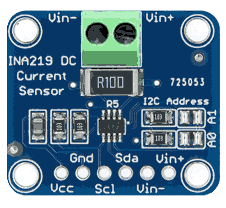
The INA219, manufactured by Adafruit (Part ID: INA219), is a high-side current shunt monitor with an I2C interface. It is designed to measure both current and voltage, enabling accurate power monitoring in a wide range of applications. This component is particularly useful for tracking power consumption in devices, making it ideal for energy-efficient designs and battery-powered systems.
Explore Projects Built with INA219
 Open Project in Cirkit Designer
 Open Project in Cirkit Designer
 Open Project in Cirkit Designer
 Open Project in Cirkit Designer
Explore Projects Built with INA219
Open Project in Cirkit DesignerOpen Project in Cirkit DesignerOpen Project in Cirkit DesignerOpen Project in Cirkit DesignerCommon Applications and Use Cases
- Battery monitoring in portable devices
- Power consumption analysis in IoT devices
- Solar power systems
- Motor current monitoring
- General-purpose power management in embedded systems
Technical Specifications
The INA219 offers precise measurements of current, voltage, and power with minimal power consumption. Below are the key technical details:
| Parameter | Value |
|---|---|
| Operating Voltage (Vcc) | 3.0V to 5.5V |
| Bus Voltage Range | 0V to 26V |
| Current Measurement Range | ±3.2A (with default 0.1Ω shunt resistor) |
| Shunt Voltage Range | ±320mV |
| Communication Interface | I2C |
| Default I2C Address | 0x40 (configurable to 0x41, 0x44, or 0x45) |
| Resolution | 12-bit |
| Accuracy | ±1% (typical) |
| Operating Temperature | -40°C to +125°C |
Pin Configuration and Descriptions
The INA219 module has the following pinout:
| Pin | Name | Description |
|---|---|---|
| 1 | VCC | Power supply input (3.0V to 5.5V). Connect to the microcontroller's power source. |
| 2 | GND | Ground connection. |
| 3 | SDA | I2C data line. Connect to the microcontroller's SDA pin. |
| 4 | SCL | I2C clock line. Connect to the microcontroller's SCL pin. |
| 5 | VIN+ | Positive input for the load being monitored. |
| 6 | VIN- | Negative input for the load being monitored. |
Usage Instructions
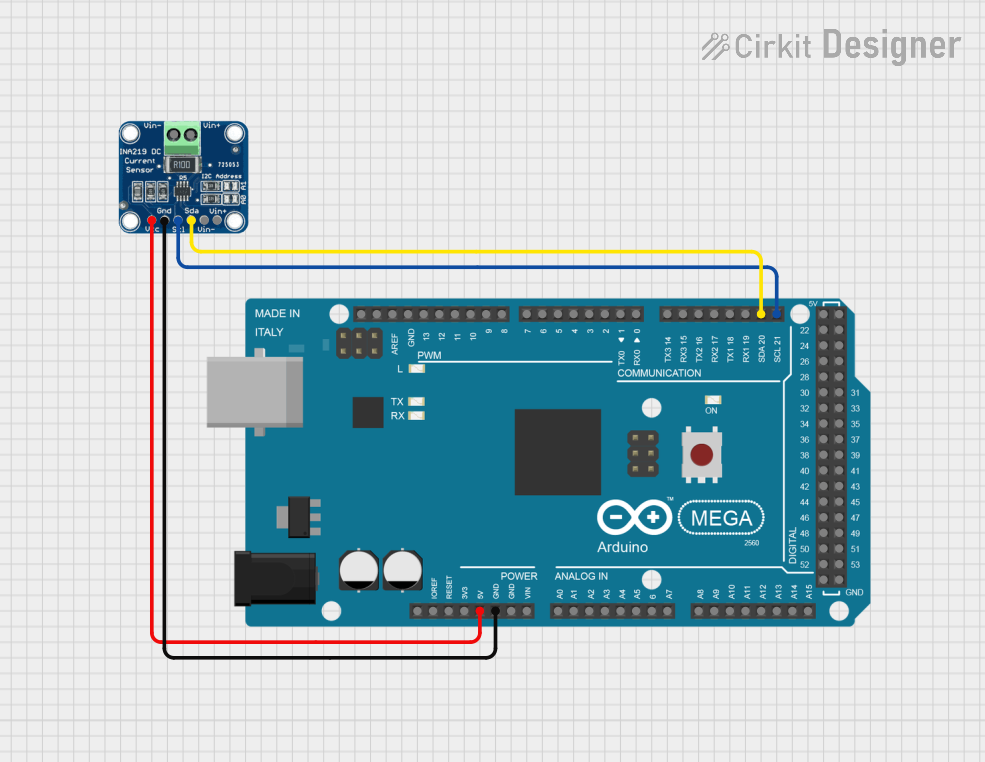
The INA219 is straightforward to use in a circuit. Follow these steps to integrate it into your project:
Connecting the INA219
- Power Supply: Connect the
VCCpin to a 3.3V or 5V power source and theGNDpin to ground. - I2C Communication: Connect the
SDAandSCLpins to the corresponding I2C pins on your microcontroller. Use pull-up resistors (typically 4.7kΩ) if not already present on the board. - Load Connection:
- Connect the
VIN+pin to the positive terminal of the load. - Connect the
VIN-pin to the negative terminal of the load or the power source's ground.
- Connect the
Important Considerations
- Ensure the shunt resistor is properly rated for the expected current range.
- The default I2C address is
0x40. If multiple INA219 modules are used, configure their addresses using the onboard solder jumpers. - Avoid exceeding the maximum bus voltage of 26V to prevent damage to the module.
Example Code for Arduino UNO
Below is an example of how to use the INA219 with an Arduino UNO to measure current, voltage, and power:
#include <Wire.h>
#include <Adafruit_INA219.h>

// Create an instance of the INA219 class
Adafruit_INA219 ina219;

void setup() {
  Serial.begin(9600); // Initialize serial communication at 9600 baud
  while (!Serial) {
    delay(10); // Wait for the serial monitor to open
  }

  // Initialize the INA219 sensor
  if (!ina219.begin()) {
    Serial.println("Failed to find INA219 chip");
    while (1) {
      delay(10); // Halt execution if the sensor is not found
    }
  }
  Serial.println("INA219 initialized successfully");
}

void loop() {
  float shuntVoltage = ina219.getShuntVoltage_mV(); // Get shunt voltage in mV
  float busVoltage = ina219.getBusVoltage_V();     // Get bus voltage in V
  float current_mA = ina219.getCurrent_mA();       // Get current in mA
  float power_mW = ina219.getPower_mW();           // Get power in mW

  // Print the measurements to the serial monitor
  Serial.print("Bus Voltage: ");
  Serial.print(busVoltage);
  Serial.println(" V");

  Serial.print("Shunt Voltage: ");
  Serial.print(shuntVoltage);
  Serial.println(" mV");

  Serial.print("Current: ");
  Serial.print(current_mA);
  Serial.println(" mA");

  Serial.print("Power: ");
  Serial.print(power_mW);
  Serial.println(" mW");

  Serial.println("-----------------------------");
  delay(1000); // Wait 1 second before the next reading
}
Best Practices
- Use short, thick wires for the load connections to minimize resistance and measurement errors.
- Calibrate the INA219 for your specific shunt resistor if you replace the default one.
- Avoid noisy environments or use proper shielding to ensure accurate I2C communication.
Troubleshooting and FAQs
Common Issues
INA219 Not Detected on I2C Bus
- Cause: Incorrect wiring or I2C address mismatch.
- Solution: Verify the connections and ensure the correct I2C address is used in the code.
Inaccurate Measurements
- Cause: Incorrect shunt resistor value or poor connections.
- Solution: Check the shunt resistor value and ensure all connections are secure.
Overheating
- Cause: Excessive current through the shunt resistor.
- Solution: Ensure the current does not exceed the rated capacity of the shunt resistor.
FAQs
Q: Can the INA219 measure negative currents?
A: Yes, the INA219 can measure bidirectional currents if configured appropriately.
Q: How do I change the I2C address of the INA219?
A: Modify the solder jumpers on the module to set a new address. Refer to the module's datasheet for details.
Q: What is the maximum current the INA219 can measure?
A: The maximum current depends on the shunt resistor value. With the default 0.1Ω resistor, it can measure up to ±3.2A.
Q: Can I use the INA219 with a 3.3V microcontroller?
A: Yes, the INA219 is compatible with both 3.3V and 5V systems.