Cirkit Designer Logo
Cirkit Designer
Your all-in-one circuit design IDE
Home / 
Component Documentation

How to Use NEMA23: Examples, Pinouts, and Specs

Image of NEMA23
Cirkit Designer LogoDesign with NEMA23 in Cirkit Designer

Introduction

The NEMA23 stepper motor is a widely used actuator that converts electrical pulses into discrete mechanical movements. The motor is part of the National Electrical Manufacturers Association (NEMA) standard, with a 2.3-inch faceplate. It is known for its robustness, precision, and relatively high torque capabilities, making it an ideal choice for CNC machines, 3D printers, robotics, and other applications requiring precise control of position and speed.

Explore Projects Built with NEMA23

Use Cirkit Designer to design, explore, and prototype these projects online. Some projects support real-time simulation. Click "Open Project" to start designing instantly!
Arduino Mega 2560 and TB6600 Stepper Motor Driver for Automated Control with NEMA 23 Motor
Image of Project: A project utilizing NEMA23 in a practical application
This circuit controls a NEMA 23 stepper motor using a TB6600 driver, managed by an Arduino Mega 2560. It also includes a solenoid valve and relays for additional control, with various switches and sensors for input, all powered by a 5V power supply and a switching power supply.
Cirkit Designer LogoOpen Project in Cirkit Designer
VINT Hub-Controlled Multi-Stepper Motor System
Image of ENPH454: A project utilizing NEMA23 in a practical application
This circuit consists of a VINT Hub Phidget connected to four 4A Stepper Phidgets, which in turn are connected to four NEMA23 stepper motors. The VINT Hub Phidget interfaces with the stepper controllers, likely for the purpose of controlling the stepper motors. A power supply is connected to all the stepper controllers to provide the necessary voltage, and a Square FSR (Force Sensitive Resistor) with a resistor is connected to the VINT Hub, possibly for sensing force or pressure.
Cirkit Designer LogoOpen Project in Cirkit Designer
Arduino-Controlled Nema 17 Stepper Motor System with TB6600 Drivers
Image of stepper: A project utilizing NEMA23 in a practical application
This circuit is designed to control three Nema 17 stepper motors using TB6600 stepper motor drivers, with an Arduino Mega 2560 microcontroller providing the control signals. A power transformer steps down the voltage to 24V for the motor drivers. The embedded code for the Arduino is currently a placeholder, requiring further development for motor control.
Cirkit Designer LogoOpen Project in Cirkit Designer
Arduino UNO Stepper Motor Controller with Keypad Shield and Relay Integration
Image of `tig circuite: A project utilizing NEMA23 in a practical application
This circuit controls a NEMA 23 stepper motor using a DM542 stepper driver, managed by an Arduino UNO. It includes a keypad shield for user input, limit switches for position feedback, and a relay module for controlling additional devices, with an emergency stop and indicator lamps for safety and status indication.
Cirkit Designer LogoOpen Project in Cirkit Designer

Explore Projects Built with NEMA23

Use Cirkit Designer to design, explore, and prototype these projects online. Some projects support real-time simulation. Click "Open Project" to start designing instantly!
Image of Project: A project utilizing NEMA23 in a practical application
Arduino Mega 2560 and TB6600 Stepper Motor Driver for Automated Control with NEMA 23 Motor
This circuit controls a NEMA 23 stepper motor using a TB6600 driver, managed by an Arduino Mega 2560. It also includes a solenoid valve and relays for additional control, with various switches and sensors for input, all powered by a 5V power supply and a switching power supply.
Cirkit Designer LogoOpen Project in Cirkit Designer
Image of ENPH454: A project utilizing NEMA23 in a practical application
VINT Hub-Controlled Multi-Stepper Motor System
This circuit consists of a VINT Hub Phidget connected to four 4A Stepper Phidgets, which in turn are connected to four NEMA23 stepper motors. The VINT Hub Phidget interfaces with the stepper controllers, likely for the purpose of controlling the stepper motors. A power supply is connected to all the stepper controllers to provide the necessary voltage, and a Square FSR (Force Sensitive Resistor) with a resistor is connected to the VINT Hub, possibly for sensing force or pressure.
Cirkit Designer LogoOpen Project in Cirkit Designer
Image of stepper: A project utilizing NEMA23 in a practical application
Arduino-Controlled Nema 17 Stepper Motor System with TB6600 Drivers
This circuit is designed to control three Nema 17 stepper motors using TB6600 stepper motor drivers, with an Arduino Mega 2560 microcontroller providing the control signals. A power transformer steps down the voltage to 24V for the motor drivers. The embedded code for the Arduino is currently a placeholder, requiring further development for motor control.
Cirkit Designer LogoOpen Project in Cirkit Designer
Image of `tig circuite: A project utilizing NEMA23 in a practical application
Arduino UNO Stepper Motor Controller with Keypad Shield and Relay Integration
This circuit controls a NEMA 23 stepper motor using a DM542 stepper driver, managed by an Arduino UNO. It includes a keypad shield for user input, limit switches for position feedback, and a relay module for controlling additional devices, with an emergency stop and indicator lamps for safety and status indication.
Cirkit Designer LogoOpen Project in Cirkit Designer

Technical Specifications

General Characteristics

  • Frame Size: 2.3 inch (58.4 mm)
  • Step Angle: Typically 1.8 degrees (200 steps per revolution)
  • Phase: Usually 2 phases

Electrical Specifications

Parameter Value Range Typical Value
Rated Voltage 2.5V to 10V 3.3V
Rated Current 1A to 5A 2.8A
Resistance per Phase 0.5Ω to 10Ω 1.65Ω
Inductance per Phase 1mH to 20mH 3.8mH
Holding Torque 0.5Nm to 3Nm 1.26Nm

Mechanical Specifications

Parameter Value
Rotor Inertia 275 g·cm²
Weight Approximately 1.1 kg

Pin Configuration and Descriptions

Pin Number Description
1 Coil A+
2 Coil A-
3 Coil B+
4 Coil B-
5 (Optional) Center tap for Coil A
6 (Optional) Center tap for Coil B

Usage Instructions

Connecting to a Circuit

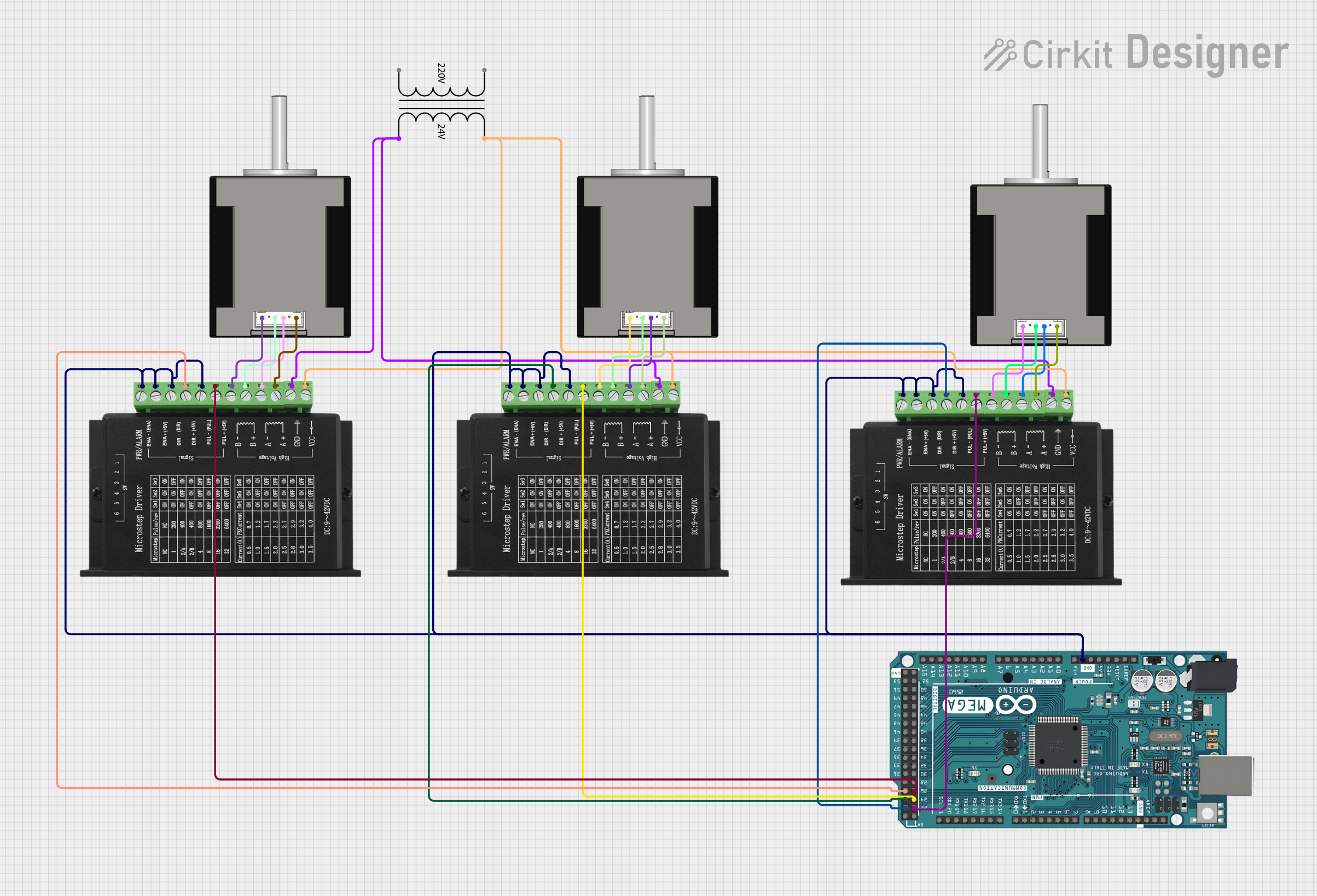
To use the NEMA23 stepper motor, you will need a stepper motor driver capable of supplying the appropriate current and voltage. The driver will have inputs for step and direction signals, which can be controlled by a microcontroller such as an Arduino UNO.

  1. Connect the motor coils to the driver. Ensure that Coil A and Coil B are connected to the corresponding outputs on the driver.
  2. Connect the driver's power supply, ensuring it matches the motor's rated voltage and can supply the necessary current.
  3. Connect the step and direction inputs from the driver to the microcontroller.

Best Practices

  • Use a current limiting driver to prevent damage to the motor.
  • Ensure that the motor is mounted securely to prevent vibrations and resonance.
  • Use a heatsink or cooling system if the motor is running at high currents for extended periods.

Example Code for Arduino UNO

#include <Stepper.h>

// Change these values based on your motor's specifications
const int stepsPerRevolution = 200;  // typically 200 steps for a NEMA23
const int stepPin = 3;               // Connect this to the driver's step input
const int dirPin = 4;                // Connect this to the driver's direction input

Stepper myStepper(stepsPerRevolution, stepPin, dirPin);

void setup() {
  myStepper.setSpeed(60); // Set the speed to 60 RPM
}

void loop() {
  myStepper.step(stepsPerRevolution); // Move one revolution in one direction
  delay(500);
  myStepper.step(-stepsPerRevolution); // Move one revolution in the other direction
  delay(500);
}

Troubleshooting and FAQs

Common Issues

  • Motor does not turn: Check wiring connections, ensure the power supply is adequate, and verify that the driver is functioning correctly.
  • Motor stalls or misses steps: This could be due to insufficient current, mechanical load exceeding the motor's torque, or an incorrect step sequence. Adjust the current limit on the driver and check the mechanical system for binding or excessive friction.
  • Motor overheats: Ensure the current settings are within the motor's specifications and improve cooling if necessary.

FAQs

Q: Can I run the NEMA23 motor at a higher voltage than rated? A: Yes, using a higher voltage with proper current control can lead to better performance, but ensure the driver can handle the increased voltage and that the current does not exceed the motor's ratings.

Q: How do I determine the correct current limit for my motor? A: The current limit should be set based on the motor's rated current. Consult the motor's datasheet and the driver's manual for specific instructions.

Q: What is the difference between unipolar and bipolar configurations? A: Unipolar motors have center taps on each coil, allowing for simpler driving circuits but generally lower torque. Bipolar motors do not have center taps and are driven by reversing the current in each coil, resulting in higher torque.

Q: How can I increase the torque of my NEMA23 motor? A: Increasing the current within the motor's rated specifications, using a higher voltage with proper current control, and reducing the speed can increase torque. Additionally, using microstepping can also improve torque at lower speeds.

For further assistance, consult the manufacturer's datasheet and the support forums for the specific driver you are using.