How to Use USB-TTL: Examples, Pinouts, and Specs
Introduction
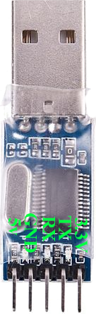
The USB-TTL converter, manufactured by Prolific, is a versatile electronic component designed to facilitate serial communication between a USB port and devices operating at TTL (Transistor-Transistor Logic) voltage levels. This component is widely used for programming microcontrollers, debugging embedded systems, and interfacing with various electronic modules such as sensors, displays, and communication devices.
Explore Projects Built with USB-TTL


Explore Projects Built with USB-TTL
Common Applications and Use Cases
- Programming microcontrollers (e.g., Arduino, ESP8266, ESP32, etc.)
- Debugging and monitoring serial data from embedded systems
- Interfacing with TTL-level devices such as GPS modules, GSM modules, and sensors
- Creating custom USB-to-serial communication tools
- Prototyping and testing serial communication protocols
Technical Specifications
The Prolific USB-TTL converter is designed to provide reliable and efficient communication between USB and TTL devices. Below are the key technical details:
General Specifications
- Manufacturer: Prolific
- Model: USB-TTL Converter
- USB Standard: USB 2.0 (compatible with USB 1.1 and USB 3.0)
- Supported Baud Rates: 75 bps to 12 Mbps
- TTL Voltage Levels: 3.3V and 5V (selectable)
- Operating Temperature: -40°C to 85°C
- Driver Support: Windows, macOS, Linux
Pin Configuration and Descriptions
The USB-TTL converter typically features a 6-pin header for TTL communication. Below is the pinout and description:
| Pin | Name | Description |
|---|---|---|
| 1 | GND | Ground (0V reference) |
| 2 | TXD | Transmit Data (output from USB-TTL) |
| 3 | RXD | Receive Data (input to USB-TTL) |
| 4 | VCC | Power output (3.3V or 5V, selectable) |
| 5 | RTS | Request to Send (optional control pin) |
| 6 | CTS | Clear to Send (optional control pin) |
Note: Some USB-TTL converters may omit RTS and CTS pins if hardware flow control is not supported.
Usage Instructions
How to Use the USB-TTL Converter in a Circuit
Connect the USB-TTL to Your Computer:
- Plug the USB-TTL converter into an available USB port on your computer.
- Install the required Prolific drivers (if not already installed). These can be downloaded from the Prolific website.
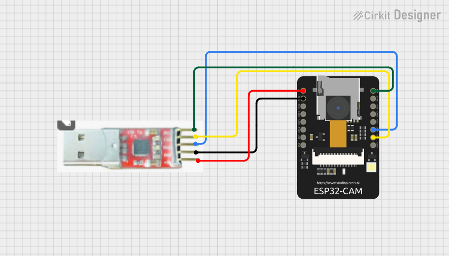
Connect the TTL Device:
- Use jumper wires to connect the USB-TTL pins to the corresponding pins on your TTL device:
- GND: Connect to the ground pin of the TTL device.
- TXD: Connect to the RX (receive) pin of the TTL device.
- RXD: Connect to the TX (transmit) pin of the TTL device.
- VCC: Connect to the power input of the TTL device (ensure the voltage matches the device's requirements).
- Use jumper wires to connect the USB-TTL pins to the corresponding pins on your TTL device:
Select Voltage Level:
- If your USB-TTL converter has a voltage selection jumper, set it to 3.3V or 5V based on the TTL device's operating voltage.
Open a Serial Communication Tool:
- Use a serial terminal program (e.g., PuTTY, Tera Term, or Arduino IDE Serial Monitor) to communicate with the TTL device.
- Configure the baud rate and other serial settings to match the TTL device's requirements.
Important Considerations and Best Practices
- Voltage Compatibility: Ensure the voltage level (3.3V or 5V) of the USB-TTL converter matches the TTL device to avoid damage.
- Cross-Connection of TX and RX: Always connect the TXD pin of the USB-TTL to the RX pin of the TTL device, and vice versa.
- Driver Installation: Verify that the Prolific driver is correctly installed on your computer. Without the driver, the USB-TTL may not be recognized.
- Avoid Overloading: Do not draw excessive current from the VCC pin of the USB-TTL converter. Check the datasheet for the maximum current rating.
Example: Connecting USB-TTL to Arduino UNO
The USB-TTL converter can be used to program or communicate with an Arduino UNO. Below is an example of how to use it with the Arduino IDE:
Wiring Diagram
| USB-TTL Pin | Arduino UNO Pin |
|---|---|
| GND | GND |
| TXD | RX (Pin 0) |
| RXD | TX (Pin 1) |
| VCC | 5V |
Sample Code
// Example: Sending data from Arduino to a computer via USB-TTL
// Open the Serial Monitor to view the output.

void setup() {
  Serial.begin(9600); // Initialize serial communication at 9600 baud
}

void loop() {
  Serial.println("Hello from Arduino!"); // Send a message to the computer
  delay(1000); // Wait for 1 second
}
Note: Disconnect the USB-TTL converter from the Arduino UNO while uploading new sketches to avoid conflicts with the onboard USB interface.
Troubleshooting and FAQs
Common Issues and Solutions
USB-TTL Not Recognized by Computer:
- Ensure the Prolific driver is installed and up to date.
- Try a different USB port or cable.
- Check the device manager (Windows) or system profiler (macOS) to verify the USB-TTL is detected.
No Data Transmission:
- Verify the TXD and RXD connections are correctly crossed.
- Check the baud rate and serial settings in your terminal program.
- Ensure the TTL device is powered and functioning.
Incorrect Voltage Level:
- Double-check the voltage selection jumper on the USB-TTL converter.
- Ensure the TTL device operates at the selected voltage (3.3V or 5V).
Data Corruption or Noise:
- Use shorter, high-quality jumper wires to reduce interference.
- Ensure a common ground connection between the USB-TTL and the TTL device.
FAQs
Q: Can I use the USB-TTL converter to power my TTL device?
A: Yes, but ensure the current draw of the TTL device does not exceed the USB-TTL converter's maximum output current (typically 50-100mA).
Q: Is the USB-TTL converter compatible with 1.8V devices?
A: No, the USB-TTL converter supports only 3.3V and 5V logic levels. Use a level shifter for 1.8V devices.
Q: How do I check if the Prolific driver is installed?
A: On Windows, open the Device Manager and look for "Prolific USB-to-Serial Comm Port" under Ports (COM & LPT). On macOS or Linux, use the lsusb command to list connected USB devices.
Q: Can I use the USB-TTL converter with Raspberry Pi?
A: Yes, the USB-TTL converter can be used to establish a serial connection with the Raspberry Pi's GPIO UART pins. Ensure proper voltage levels and connections.
By following this documentation, you can effectively use the Prolific USB-TTL converter for a wide range of serial communication applications.