Cirkit Designer
Your all-in-one circuit design IDE
Home /
Component Documentation
How to Use MCP23017 IO Expansion Board I2C Interface 16 I/O Pins Expands: Examples, Pinouts, and Specs
Introduction
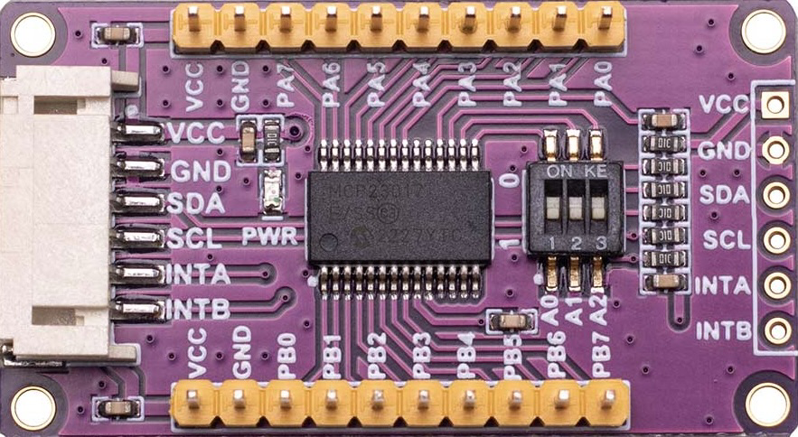
The MCP23017 IO Expansion Board, manufactured by SeenGreat (Part ID: SG IO E017), is a versatile component designed to expand the number of input/output (I/O) pins available for microcontroller projects. Utilizing the MCP23017 chip, this board provides an additional 16 I/O pins via the I2C interface, making it an ideal solution for projects requiring more I/O capabilities than what is available on standard microcontrollers.
Explore Projects Built with MCP23017 IO Expansion Board I2C Interface 16 I/O Pins Expands
MCP23017-Expanded I/O Interface with ADS1115 ADC and ESP32 Control

This circuit features two MCP23017 I/O expanders interfaced with multiple switches, allowing for the expansion of input capabilities. The MCP23017s are connected via I2C to an Olimex ESP32-EVB microcontroller, which likely manages the input states from the switches. Additionally, an Adafruit ADS1115 16-bit ADC is included, suggesting that some analog inputs are being monitored, with the ADC also interfaced with the ESP32 via I2C.
I2C-Controlled Relay Switching with ESP32 and MCP23017 for Home Automation

This circuit appears to be a control system utilizing two MCP23017 I/O expanders interfaced with an Olimex ESP32-EVB microcontroller via I2C communication, as indicated by the SDA and SCL connections with pull-up resistors. The MCP23017 expanders control an 8-channel relay module, allowing the microcontroller to switch various loads, potentially for home automation or industrial control. Additionally, there is an Adafruit ADS1115 16-bit ADC for analog signal measurement, and several heating actuators and a thermostat are connected, suggesting temperature control functionality.
Arduino UNO with MCP23017 IO Expansion and TTP233 Touch Sensors Interface
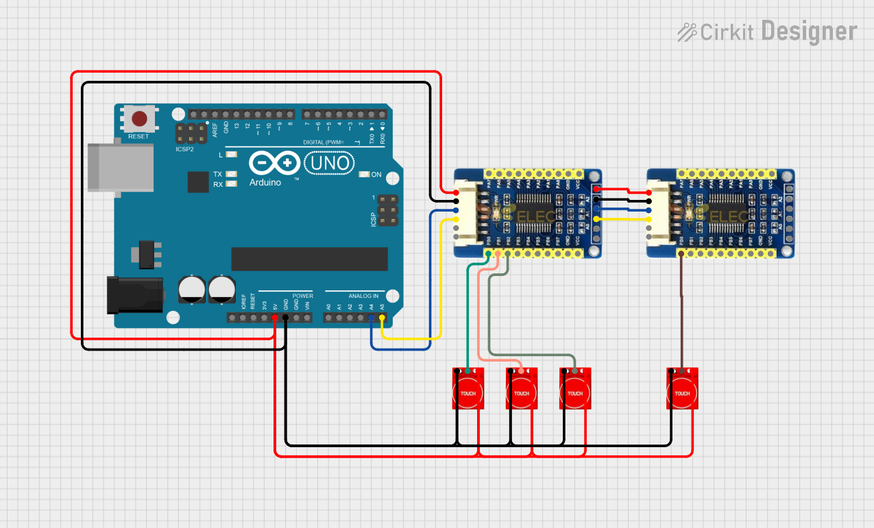
This circuit utilizes an Arduino UNO microcontroller to interface with two MCP23017 I/O expansion boards via I2C communication, expanding the number of input pins available. Four TTP233 touch sensors are connected to the input pins of the MCP23017 boards. The Arduino monitors the state of these touch sensors and outputs a serial message when a touch event is detected on any sensor.
ESP32-Based I2C Communication Hub with Multiplexer and Expander

This circuit features an Olimex ESP32-EVB microcontroller unit (MCU) for processing and connectivity, interfaced with an MCP23017 I/O expander and an Adafruit TCA9548A I2C multiplexer to expand the number of I/O lines and allow multiple I2C devices to communicate with the MCU over the same bus. Pull-up resistors are connected to the I2C lines for proper bus operation, and both the MCP23017 and TCA9548A have their reset lines pulled high, likely for normal operation without external reset control.
Explore Projects Built with MCP23017 IO Expansion Board I2C Interface 16 I/O Pins Expands
MCP23017-Expanded I/O Interface with ADS1115 ADC and ESP32 Control
This circuit features two MCP23017 I/O expanders interfaced with multiple switches, allowing for the expansion of input capabilities. The MCP23017s are connected via I2C to an Olimex ESP32-EVB microcontroller, which likely manages the input states from the switches. Additionally, an Adafruit ADS1115 16-bit ADC is included, suggesting that some analog inputs are being monitored, with the ADC also interfaced with the ESP32 via I2C.
I2C-Controlled Relay Switching with ESP32 and MCP23017 for Home Automation
This circuit appears to be a control system utilizing two MCP23017 I/O expanders interfaced with an Olimex ESP32-EVB microcontroller via I2C communication, as indicated by the SDA and SCL connections with pull-up resistors. The MCP23017 expanders control an 8-channel relay module, allowing the microcontroller to switch various loads, potentially for home automation or industrial control. Additionally, there is an Adafruit ADS1115 16-bit ADC for analog signal measurement, and several heating actuators and a thermostat are connected, suggesting temperature control functionality.
Arduino UNO with MCP23017 IO Expansion and TTP233 Touch Sensors Interface
This circuit utilizes an Arduino UNO microcontroller to interface with two MCP23017 I/O expansion boards via I2C communication, expanding the number of input pins available. Four TTP233 touch sensors are connected to the input pins of the MCP23017 boards. The Arduino monitors the state of these touch sensors and outputs a serial message when a touch event is detected on any sensor.
ESP32-Based I2C Communication Hub with Multiplexer and Expander
This circuit features an Olimex ESP32-EVB microcontroller unit (MCU) for processing and connectivity, interfaced with an MCP23017 I/O expander and an Adafruit TCA9548A I2C multiplexer to expand the number of I/O lines and allow multiple I2C devices to communicate with the MCU over the same bus. Pull-up resistors are connected to the I2C lines for proper bus operation, and both the MCP23017 and TCA9548A have their reset lines pulled high, likely for normal operation without external reset control.
Common Applications and Use Cases
- Home Automation: Control multiple devices such as lights, fans, and sensors.
- Robotics: Manage multiple sensors, actuators, and motors.
- Industrial Automation: Interface with various industrial sensors and actuators.
- Prototyping: Expand I/O capabilities for complex prototypes and projects.
Technical Specifications
Key Technical Details
| Parameter | Value |
|---|---|
| Operating Voltage | 1.8V to 5.5V |
| I/O Pins | 16 |
| Communication | I2C |
| I2C Address Range | 0x20 to 0x27 (configurable) |
| Maximum Current | 25mA per pin |
| Package Type | DIP-28, SOIC-28 |
Pin Configuration and Descriptions
MCP23017 Pin Configuration
| Pin No. | Pin Name | Description |
|---|---|---|
| 1 | GPA0 | General Purpose I/O Pin 0 (Port A) |
| 2 | GPA1 | General Purpose I/O Pin 1 (Port A) |
| 3 | GPA2 | General Purpose I/O Pin 2 (Port A) |
| 4 | GPA3 | General Purpose I/O Pin 3 (Port A) |
| 5 | GPA4 | General Purpose I/O Pin 4 (Port A) |
| 6 | GPA5 | General Purpose I/O Pin 5 (Port A) |
| 7 | GPA6 | General Purpose I/O Pin 6 (Port A) |
| 8 | GPA7 | General Purpose I/O Pin 7 (Port A) |
| 9 | VSS | Ground |
| 10 | OSC1 | Oscillator Pin 1 (optional) |
| 11 | OSC2 | Oscillator Pin 2 (optional) |
| 12 | SCL | I2C Clock Line |
| 13 | SDA | I2C Data Line |
| 14 | A0 | I2C Address Pin 0 |
| 15 | A1 | I2C Address Pin 1 |
| 16 | A2 | I2C Address Pin 2 |
| 17 | RESET | Reset (active low) |
| 18 | INTB | Interrupt Output for Port B |
| 19 | INTA | Interrupt Output for Port A |
| 20 | VDD | Power Supply |
| 21 | GPB0 | General Purpose I/O Pin 0 (Port B) |
| 22 | GPB1 | General Purpose I/O Pin 1 (Port B) |
| 23 | GPB2 | General Purpose I/O Pin 2 (Port B) |
| 24 | GPB3 | General Purpose I/O Pin 3 (Port B) |
| 25 | GPB4 | General Purpose I/O Pin 4 (Port B) |
| 26 | GPB5 | General Purpose I/O Pin 5 (Port B) |
| 27 | GPB6 | General Purpose I/O Pin 6 (Port B) |
| 28 | GPB7 | General Purpose I/O Pin 7 (Port B) |
Usage Instructions
How to Use the Component in a Circuit
- Power Supply: Connect the VDD pin to a power supply (1.8V to 5.5V) and the VSS pin to ground.
- I2C Interface: Connect the SCL (clock) and SDA (data) lines to the corresponding I2C pins on your microcontroller.
- Address Configuration: Set the I2C address by connecting A0, A1, and A2 to either VDD or VSS. The default address is 0x20.
- I/O Pins: Connect your devices to the GPA0-GPA7 and GPB0-GPB7 pins.
- Interrupts (Optional): Connect INTA and INTB to your microcontroller if you need interrupt functionality.
Important Considerations and Best Practices
- Pull-up Resistors: Ensure that the I2C lines (SCL and SDA) have appropriate pull-up resistors (typically 4.7kΩ).
- Current Limitation: Do not exceed 25mA per I/O pin to avoid damaging the chip.
- Debouncing: Implement debouncing for input pins to avoid false triggering.
- Address Conflicts: Ensure that the I2C address does not conflict with other devices on the same bus.
Example Code for Arduino UNO
#include <Wire.h>
#include "Adafruit_MCP23017.h"

// Create an MCP23017 object
Adafruit_MCP23017 mcp;

void setup() {
  // Start the I2C communication
  Wire.begin();

  // Initialize the MCP23017 with the default address (0x20)
  mcp.begin();

  // Set pin GPA0 as an output
  mcp.pinMode(0, OUTPUT);

  // Set pin GPA1 as an input with pull-up resistor
  mcp.pinMode(1, INPUT);
  mcp.pullUp(1, HIGH);

  // Initialize serial communication for debugging
  Serial.begin(9600);
}

void loop() {
  // Read the state of pin GPA1
  uint8_t pinState = mcp.digitalRead(1);

  // Print the state to the serial monitor
  Serial.print("GPA1 state: ");
  Serial.println(pinState);

  // Toggle the state of pin GPA0
  mcp.digitalWrite(0, !pinState);

  // Wait for 500 milliseconds
  delay(500);
}
Troubleshooting and FAQs
Common Issues Users Might Face
I2C Communication Failure:
- Solution: Check the connections for SCL and SDA. Ensure pull-up resistors are in place.
Incorrect I/O Pin Behavior:
- Solution: Verify the pinMode settings and ensure the correct pin numbers are used.
Address Conflicts:
- Solution: Ensure the I2C address is unique and does not conflict with other devices on the bus.
Solutions and Tips for Troubleshooting
- Check Connections: Ensure all connections are secure and correctly placed.
- Use a Multimeter: Verify voltage levels and continuity of connections.
- Consult Datasheet: Refer to the MCP23017 datasheet for detailed information and advanced configurations.
- Debugging: Use serial print statements to debug and monitor the state of I/O pins.
By following this documentation, users can effectively integrate the MCP23017 IO Expansion Board into their projects, expanding their microcontroller's I/O capabilities with ease.