
How to Use PLUG: Examples, Pinouts, and Specs
 Design with PLUG in Cirkit Designer
Introduction
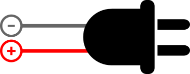
A plug is a device that connects an electrical appliance to a power source, allowing electricity to flow into the appliance. It is an essential component in electrical systems, enabling the safe and efficient transfer of power. Plugs are commonly used in household appliances, industrial equipment, and portable devices. They come in various types and configurations to suit different power standards and applications.
Explore Projects Built with PLUG
 Open Project in Cirkit Designer
 Open Project in Cirkit Designer
 Open Project in Cirkit Designer
 Open Project in Cirkit Designer
Explore Projects Built with PLUG
Open Project in Cirkit DesignerOpen Project in Cirkit DesignerOpen Project in Cirkit DesignerOpen Project in Cirkit DesignerCommon Applications and Use Cases
- Powering household appliances such as refrigerators, televisions, and lamps.
- Connecting industrial machinery to power outlets.
- Charging portable devices like laptops and smartphones.
- Providing power to tools and equipment in workshops.
Technical Specifications
General Specifications
| Parameter | Value/Description |
|---|---|
| Voltage Rating | Typically 110V-240V AC (varies by region) |
| Current Rating | Commonly 6A, 10A, 13A, or 15A |
| Frequency | 50Hz or 60Hz |
| Material | Plastic or thermoset for insulation, |
| with metal prongs for conductivity | |
| Safety Features | Insulated pins, grounding pin, |
| and fuse (in some types) |
Pin Configuration and Descriptions
Plugs typically have two or three pins, depending on the type and grounding requirements.
Example: Three-Pin Plug (Type G - UK Standard)
| Pin Name | Description |
|---|---|
| Live (L) | Carries the current from the power source. |
| Neutral (N) | Completes the circuit back to the power source. |
| Ground (G) | Provides a safety path for fault currents. |
Example: Two-Pin Plug (Type A - North America)
| Pin Name | Description |
|---|---|
| Live (L) | Carries the current from the power source. |
| Neutral (N) | Completes the circuit back to the power source. |
Usage Instructions
How to Use the Plug in a Circuit
- Select the Appropriate Plug Type: Ensure the plug matches the voltage and current requirements of your appliance and the power outlet.
- Inspect the Plug: Check for any visible damage, such as frayed wires or cracked insulation.
- Connect to the Appliance: Securely attach the plug to the appliance's power cord, ensuring proper wiring:
- Connect the live wire to the live pin.
- Connect the neutral wire to the neutral pin.
- If applicable, connect the ground wire to the ground pin.
- Insert into the Power Outlet: Firmly insert the plug into the outlet, ensuring a snug fit.
- Turn on the Appliance: Switch on the appliance and verify proper operation.
Important Considerations and Best Practices
- Always use plugs that comply with local electrical standards.
- Avoid overloading the plug by connecting appliances that exceed its current rating.
- Use plugs with built-in fuses for added safety.
- Ensure proper grounding for appliances with metal casings to prevent electric shocks.
- Do not use damaged plugs or cords, as they pose a fire and safety hazard.
Example: Connecting a Plug to an Arduino UNO
If you are using a plug to power an Arduino UNO via an adapter, follow these steps:
- Use a plug with the correct voltage and current rating for the adapter (e.g., 5V, 1A).
- Connect the adapter to the plug and insert it into a power outlet.
- Plug the adapter's output into the Arduino UNO's power jack.
Sample Arduino Code for Testing
// This code blinks an LED connected to pin 13 of the Arduino UNO.
// Ensure the Arduino is powered via the plug and adapter.

void setup() {
  pinMode(13, OUTPUT); // Set pin 13 as an output pin
}

void loop() {
  digitalWrite(13, HIGH); // Turn the LED on
  delay(1000);            // Wait for 1 second
  digitalWrite(13, LOW);  // Turn the LED off
  delay(1000);            // Wait for 1 second
}
Troubleshooting and FAQs
Common Issues Users Might Face
Plug Does Not Fit the Outlet:
- Ensure the plug type matches the outlet standard in your region.
- Use an appropriate adapter if necessary.
Appliance Does Not Power On:
- Check the plug's wiring for loose connections.
- Verify that the outlet is supplying power.
- Inspect the fuse (if present) and replace it if blown.
Overheating Plug:
- Ensure the appliance's current draw does not exceed the plug's rating.
- Check for damaged or frayed wires.
Electric Shocks When Touching the Appliance:
- Verify proper grounding of the plug and appliance.
- Replace the plug if insulation is damaged.
Solutions and Tips for Troubleshooting
- Use a multimeter to check for continuity and proper wiring.
- Replace damaged plugs immediately to avoid safety hazards.
- Consult a licensed electrician for complex issues or repairs.
FAQs
Q: Can I use a two-pin plug for a three-pin outlet?
A: Yes, but only for appliances that do not require grounding. Ensure the appliance is double-insulated.
Q: How do I know if the plug's fuse is blown?
A: Use a multimeter to check for continuity across the fuse. If there is no continuity, replace the fuse.
Q: Can I repair a damaged plug myself?
A: Yes, if you are familiar with electrical wiring. Otherwise, consult a professional to ensure safety.
Q: What is the purpose of the ground pin?
A: The ground pin provides a safe path for fault currents, reducing the risk of electric shocks.