How to Use mini voltmeter 3 wire 4-100V DC: Examples, Pinouts, and Specs
Introduction
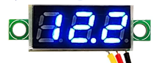
The Mini Voltmeter 3 Wire 4-100V DC is a compact and efficient device designed to measure DC voltage within a range of 4 to 100 volts. Its three-wire design ensures easy integration into a variety of electronic circuits, making it a versatile tool for hobbyists, engineers, and technicians. This voltmeter is commonly used in battery monitoring, power supply testing, and other applications requiring real-time voltage measurement.
Explore Projects Built with mini voltmeter 3 wire 4-100V DC
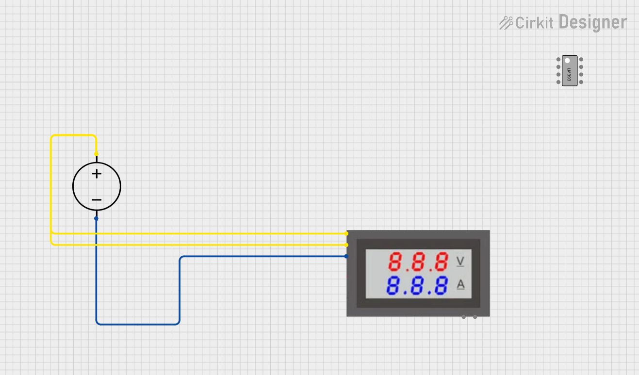
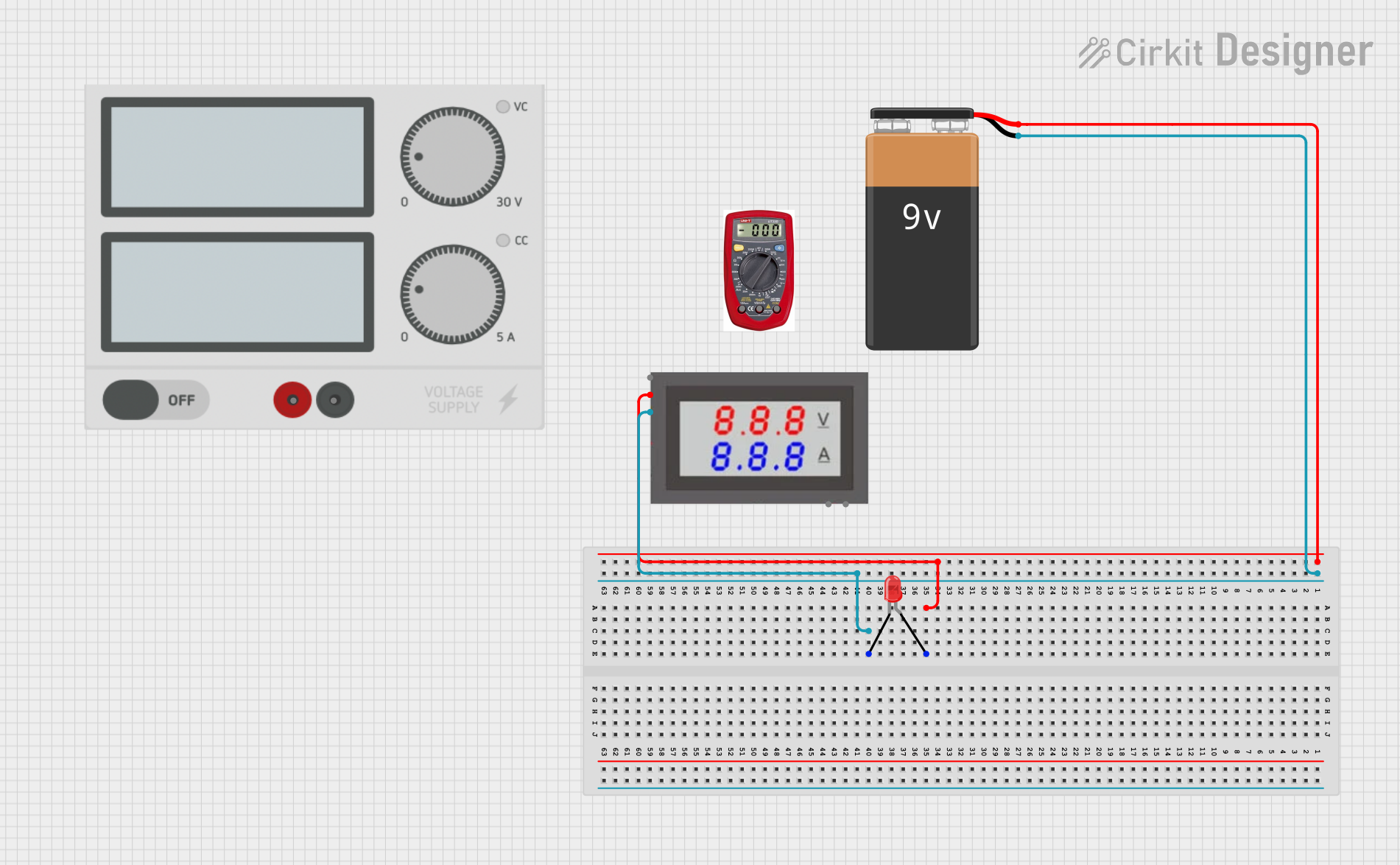

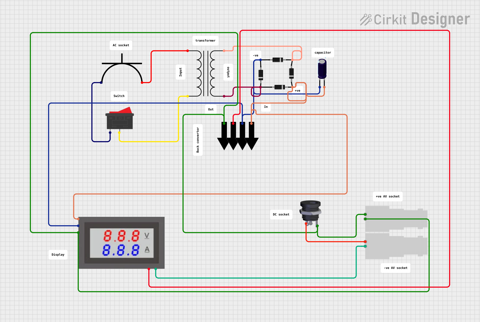
Explore Projects Built with mini voltmeter 3 wire 4-100V DC
Common Applications and Use Cases
- Monitoring battery voltage in automotive or renewable energy systems
- Testing and troubleshooting DC power supplies
- Integrating into DIY electronics projects for voltage display
- Measuring voltage in robotics and embedded systems
Technical Specifications
Key Technical Details
- Voltage Measurement Range: 4V to 100V DC
- Operating Voltage: 4V to 30V DC (separate power supply required for voltages below 4V)
- Display Type: 3-digit 7-segment LED display
- Accuracy: ±1% (typical)
- Refresh Rate: ~200ms
- Input Impedance: >100kΩ
- Wire Length: ~15-20 cm
- Dimensions: ~48mm x 29mm x 21mm
- Operating Temperature: -10°C to +65°C
Pin Configuration and Descriptions
The Mini Voltmeter has three wires for connection. The table below describes each wire:
| Wire Color | Function | Description |
|---|---|---|
| Red | Power Supply (Vcc) | Connect to a DC power source (4-30V) to power the voltmeter. |
| Black | Ground (GND) | Common ground for both power supply and voltage measurement. |
| Yellow | Voltage Measurement Input | Connect to the positive terminal of the voltage source to be measured. |
Note: The voltmeter requires a separate power supply if the measured voltage is below 4V.
Usage Instructions
How to Use the Component in a Circuit
Power the Voltmeter:
- Connect the red wire to a DC power source (4-30V).
- Connect the black wire to the ground of the power source.
Connect the Voltage to Be Measured:
- Attach the yellow wire to the positive terminal of the voltage source you want to measure.
- Ensure the black wire is connected to the ground of the voltage source.
Read the Voltage:
- Once connected, the LED display will show the measured voltage in real-time.
Important Considerations and Best Practices
- Voltage Range: Ensure the measured voltage is within the 4-100V range. Exceeding this range may damage the voltmeter.
- Separate Power Supply: If measuring a voltage below 4V, use a separate power supply (4-30V) to power the voltmeter.
- Polarity: Always connect the wires with the correct polarity. Reversing the connections may damage the device.
- Mounting: Secure the voltmeter in a stable position to avoid loose connections or damage during operation.
- Isolation: For high-voltage applications, ensure proper isolation and safety precautions to prevent electrical hazards.
Example: Connecting to an Arduino UNO
The Mini Voltmeter can be used to monitor the output voltage of an Arduino-controlled circuit. Below is an example of how to connect and use the voltmeter:
- Connect the red wire to the Arduino's 5V pin.
- Connect the black wire to the Arduino's GND pin.
- Connect the yellow wire to the positive terminal of the voltage source you want to measure.
Here is an example Arduino code to simulate a voltage source using PWM:
// Example code to generate a PWM signal for testing the Mini Voltmeter
const int pwmPin = 9; // PWM output pin

void setup() {
  pinMode(pwmPin, OUTPUT); // Set the pin as an output
}

void loop() {
  // Generate a PWM signal with varying duty cycle
  for (int dutyCycle = 0; dutyCycle <= 255; dutyCycle += 5) {
    analogWrite(pwmPin, dutyCycle); // Write PWM signal
    delay(100); // Wait for 100ms
  }
  for (int dutyCycle = 255; dutyCycle >= 0; dutyCycle -= 5) {
    analogWrite(pwmPin, dutyCycle); // Write PWM signal
    delay(100); // Wait for 100ms
  }
}
Note: The Mini Voltmeter will display the average voltage of the PWM signal. Use a capacitor across the voltage source to smooth the signal for a more stable reading.
Troubleshooting and FAQs
Common Issues and Solutions
No Display on the Voltmeter:
- Cause: Incorrect power supply connection or insufficient voltage.
- Solution: Verify that the red wire is connected to a 4-30V DC power source and the black wire is connected to ground.
Inaccurate Voltage Reading:
- Cause: Loose connections or interference from nearby components.
- Solution: Ensure all connections are secure and use short, shielded wires to minimize interference.
Display Flickering:
- Cause: Unstable power supply or noisy voltage source.
- Solution: Use a stable power supply and add a capacitor (e.g., 10µF) across the power input to filter noise.
Voltmeter Not Measuring Voltage Below 4V:
- Cause: The voltmeter's operating voltage is too low.
- Solution: Use a separate power supply (4-30V) to power the voltmeter.
FAQs
Q1: Can the Mini Voltmeter measure AC voltage?
A1: No, this voltmeter is designed for DC voltage only. Measuring AC voltage may damage the device.
Q2: Can I use the voltmeter to measure current?
A2: No, this device is specifically designed for voltage measurement. Use a current sensor or ammeter for current measurement.
Q3: What happens if I reverse the polarity of the wires?
A3: Reversing the polarity may damage the voltmeter. Always double-check the connections before powering the device.
Q4: Can I use the voltmeter with a 12V car battery?
A4: Yes, the voltmeter can measure the voltage of a 12V car battery. Ensure proper connections and polarity.
By following this documentation, you can effectively use the Mini Voltmeter 3 Wire 4-100V DC in your projects and troubleshoot common issues with ease.