How to Use GPS Breakout - XA1110 (Qwiic): Examples, Pinouts, and Specs
Introduction
The GPS Breakout - XA1110 (Qwiic), manufactured by SparkFun (Part ID: GPS-14414), is a compact and highly efficient GPS module designed for seamless integration into projects requiring precise location and time data. Built around the XA1110 chip, this module supports multiple GNSS constellations, including GPS, GLONASS, and QZSS, ensuring reliable and accurate positioning. Its Qwiic connector simplifies wiring and eliminates the need for soldering, making it ideal for rapid prototyping and development.
Explore Projects Built with GPS Breakout - XA1110 (Qwiic)

Explore Projects Built with GPS Breakout - XA1110 (Qwiic)
Common Applications
- Navigation systems for drones, robots, and vehicles
- Geolocation tracking for IoT devices
- Time synchronization for embedded systems
- Outdoor activity trackers and wearables
- Geographic data logging and mapping
Technical Specifications
The following table outlines the key technical details of the GPS Breakout - XA1110 (Qwiic):
| Parameter | Specification |
|---|---|
| Chipset | XA1110 |
| GNSS Support | GPS, GLONASS, QZSS |
| Operating Voltage | 3.3V |
| Current Consumption | ~30mA (typical) |
| Position Accuracy | <2.5m CEP (Circular Error Probable) |
| Time to First Fix (TTFF) | Cold Start: <35s, Hot Start: <1s |
| Communication Interface | I2C (Qwiic), UART |
| I2C Address | 0x10 (default) |
| Dimensions | 1.0" x 1.0" (25.4mm x 25.4mm) |
| Operating Temperature | -40°C to +85°C |
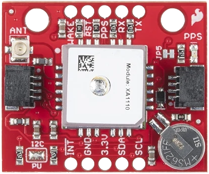
Pin Configuration and Descriptions
The GPS Breakout - XA1110 (Qwiic) features the following pinout:
| Pin | Label | Description |
|---|---|---|
| 1 | 3.3V | Power supply input (3.3V only) |
| 2 | GND | Ground connection |
| 3 | TX | UART Transmit (for serial communication) |
| 4 | RX | UART Receive (for serial communication) |
| 5 | SDA | I2C Data Line |
| 6 | SCL | I2C Clock Line |
| 7 | PPS | Pulse Per Second output for precise timing |
| 8 | RST | Reset pin (active low) |
Usage Instructions
Connecting the GPS Breakout
- Power Supply: Ensure the module is powered with a stable 3.3V source. Do not exceed this voltage to avoid damaging the module.
- I2C Connection: Use the Qwiic connector to interface with an I2C-compatible microcontroller, such as an Arduino UNO (with a Qwiic shield).
- UART Connection: Alternatively, connect the TX and RX pins to the UART pins of your microcontroller for serial communication.
- Antenna: Attach an external active GPS antenna to the U.FL connector for optimal signal reception.
Example: Using with Arduino UNO
Below is an example of how to use the GPS Breakout - XA1110 (Qwiic) with an Arduino UNO via I2C:
Required Libraries
Install the following libraries in the Arduino IDE:
Wire.h(built-in for I2C communication)SparkFun u-blox GNSS Arduino Library
Wiring Diagram
- Connect the Qwiic cable from the GPS module to the Qwiic shield on the Arduino UNO.
- Alternatively, connect the pins as follows:
SDA→ Arduino A4SCL→ Arduino A53.3V→ Arduino 3.3VGND→ Arduino GND
Arduino Code
#include <Wire.h>
#include <SparkFun_u-blox_GNSS_Arduino_Library.h> // Include the SparkFun GNSS library

SFE_UBLOX_GNSS myGNSS; // Create a GNSS object

void setup() {
  Serial.begin(9600); // Initialize serial communication for debugging
  Wire.begin();       // Initialize I2C communication

  // Initialize the GPS module
  if (myGNSS.begin() == false) {
    Serial.println("Failed to initialize GPS module. Check connections.");
    while (1); // Halt execution if initialization fails
  }

  Serial.println("GPS module initialized successfully!");
}

void loop() {
  // Check if new location data is available
  if (myGNSS.getPVT()) {
    // Print latitude, longitude, and altitude
    Serial.print("Latitude: ");
    Serial.println(myGNSS.getLatitude() / 10000000.0, 7); // Convert to decimal degrees
    Serial.print("Longitude: ");
    Serial.println(myGNSS.getLongitude() / 10000000.0, 7); // Convert to decimal degrees
    Serial.print("Altitude: ");
    Serial.println(myGNSS.getAltitude() / 1000.0, 2); // Convert to meters
  }

  delay(1000); // Wait 1 second before checking again
}
Best Practices
- Use an active GPS antenna for better signal reception, especially in areas with weak satellite visibility.
- Place the antenna in an open area, away from obstructions like walls or metal objects.
- Avoid powering the module with voltages higher than 3.3V to prevent damage.
- Use proper pull-up resistors on the I2C lines if not using the Qwiic connector.
Troubleshooting and FAQs
Common Issues
No GPS Fix:
- Ensure the antenna is connected and placed in an open area with a clear view of the sky.
- Wait for a few minutes for the module to acquire satellite signals, especially during the first use.
I2C Communication Failure:
- Verify the I2C address (default: 0x10) and ensure no address conflicts on the bus.
- Check the wiring and ensure proper connections to the SDA and SCL pins.
Module Not Powering On:
- Confirm that the power supply is 3.3V and capable of providing sufficient current (~30mA).
- Check for loose or incorrect connections.
FAQs
Q: Can the module operate at 5V?
A: No, the GPS Breakout - XA1110 is designed to operate at 3.3V only. Use a level shifter if interfacing with a 5V system.
Q: How many satellites does the module support?
A: The XA1110 chip can track up to 33 satellites simultaneously across supported GNSS constellations.
Q: What is the default baud rate for UART communication?
A: The default baud rate is 9600 bps.
Q: Can I use the module indoors?
A: While the module may work indoors near windows, signal reception is significantly better outdoors with a clear view of the sky.
Q: How do I reset the module?
A: Pull the RST pin low momentarily to reset the module.
By following this documentation, you can effectively integrate the GPS Breakout - XA1110 (Qwiic) into your projects and troubleshoot common issues.