How to Use T-ETH-Lite S3: Examples, Pinouts, and Specs
Introduction
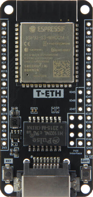
The T-ETH-Lite S3 by LILYGO (Part ID: H674) is a compact Ethernet module designed for low-power applications. It is built to provide seamless integration of network connectivity into embedded systems, making it an ideal choice for IoT devices, industrial automation, and smart home applications. With its small form factor and efficient design, the T-ETH-Lite S3 is perfect for projects requiring reliable Ethernet communication without compromising on power efficiency.
Explore Projects Built with T-ETH-Lite S3


Explore Projects Built with T-ETH-Lite S3
Common Applications
- IoT devices requiring Ethernet connectivity
- Industrial automation systems
- Smart home hubs and controllers
- Data logging and remote monitoring systems
- Low-power networked sensors
Technical Specifications
Key Technical Details
| Parameter | Value |
|---|---|
| Manufacturer | LILYGO |
| Part ID | H674 |
| Ethernet Controller | W5500 |
| Microcontroller | ESP32-S3 |
| Operating Voltage | 3.3V |
| Power Consumption | Low-power design |
| Communication Interface | SPI (for Ethernet) |
| Ethernet Speed | 10/100 Mbps |
| Dimensions | Compact form factor |
| Operating Temperature | -40°C to 85°C |
Pin Configuration and Descriptions
The T-ETH-Lite S3 module features a set of pins for power, communication, and control. Below is the pinout description:
| Pin Name | Type | Description |
|---|---|---|
| VIN | Power Input | 3.3V power input for the module |
| GND | Ground | Ground connection |
| MOSI | SPI Input | Master Out Slave In (SPI data input) |
| MISO | SPI Output | Master In Slave Out (SPI data output) |
| SCK | SPI Clock | Serial Clock for SPI communication |
| CS | SPI Control | Chip Select for SPI communication |
| RST | Reset | Resets the Ethernet controller |
| INT | Interrupt | Interrupt pin for Ethernet events |
| TX/RX | UART | Serial communication pins for debugging |
Usage Instructions
How to Use the T-ETH-Lite S3 in a Circuit
- Power Supply: Connect the VIN pin to a stable 3.3V power source and GND to ground.
- SPI Communication: Connect the SPI pins (MOSI, MISO, SCK, and CS) to the corresponding SPI pins on your microcontroller.
- Reset and Interrupt: Use the RST pin to reset the Ethernet controller when needed. The INT pin can be used to handle Ethernet-related interrupts.
- Ethernet Connection: Plug in an Ethernet cable to the RJ45 port on the module for network connectivity.
Important Considerations
- Ensure the power supply is stable and within the specified voltage range (3.3V).
- Use proper pull-up or pull-down resistors on the SPI lines if required by your microcontroller.
- Keep the Ethernet cable length within the recommended range to avoid signal degradation.
- Avoid placing the module near high-frequency components to minimize interference.
Example: Connecting to an Arduino UNO
The T-ETH-Lite S3 can be connected to an Arduino UNO using the SPI interface. Below is an example code snippet to initialize the Ethernet module and establish a basic connection:
#include <SPI.h>
#include <Ethernet.h>

// Define the MAC address and IP address for the Ethernet module
byte mac[] = { 0xDE, 0xAD, 0xBE, 0xEF, 0xFE, 0xED };
IPAddress ip(192, 168, 1, 177); // Set a static IP address

// Initialize the Ethernet server on port 80
EthernetServer server(80);

void setup() {
  // Start the serial communication for debugging
  Serial.begin(9600);

  // Initialize the Ethernet module
  if (Ethernet.begin(mac) == 0) {
    Serial.println("Failed to configure Ethernet using DHCP");
    // If DHCP fails, use a static IP address
    Ethernet.begin(mac, ip);
  }

  // Start the server
  server.begin();
  Serial.print("Server is at ");
  Serial.println(Ethernet.localIP());
}

void loop() {
  // Listen for incoming clients
  EthernetClient client = server.available();
  if (client) {
    Serial.println("New client connected");
    while (client.connected()) {
      if (client.available()) {
        char c = client.read();
        Serial.write(c); // Echo the received data to the serial monitor
        // Respond to the client
        client.println("Hello from T-ETH-Lite S3!");
      }
    }
    client.stop();
    Serial.println("Client disconnected");
  }
}
Notes:
- Replace the MAC address and IP address with values suitable for your network.
- Ensure the SPI pins on the Arduino UNO are correctly connected to the T-ETH-Lite S3.
Troubleshooting and FAQs
Common Issues and Solutions
Ethernet Module Not Initializing
- Cause: Incorrect SPI connections or power supply issues.
- Solution: Double-check the wiring and ensure the VIN pin is receiving 3.3V.
No Network Connectivity
- Cause: Incorrect MAC or IP address configuration.
- Solution: Verify the MAC and IP address settings in the code. Ensure the network router allows the assigned IP.
Intermittent Connection Drops
- Cause: Poor Ethernet cable quality or excessive cable length.
- Solution: Use a high-quality Ethernet cable and keep the length within the recommended range.
High Power Consumption
- Cause: Unnecessary peripherals or incorrect power settings.
- Solution: Disable unused peripherals and ensure the module is in low-power mode when idle.
FAQs
Q: Can the T-ETH-Lite S3 be powered with 5V?
A: No, the module operates at 3.3V. Supplying 5V may damage the module.
Q: Does the module support Wi-Fi?
A: The T-ETH-Lite S3 is primarily designed for Ethernet connectivity. However, the onboard ESP32-S3 microcontroller supports Wi-Fi if configured separately.
Q: Can I use this module with other microcontrollers?
A: Yes, the T-ETH-Lite S3 can be used with any microcontroller that supports SPI communication.
Q: How do I update the firmware?
A: Firmware updates can be performed via the ESP32-S3's programming interface using tools like the Arduino IDE or ESP-IDF.
This concludes the documentation for the T-ETH-Lite S3. For further assistance, refer to the official LILYGO resources or community forums.