How to Use Bipolar Stepper Motor (NEMA 17): Examples, Pinouts, and Specs
Introduction
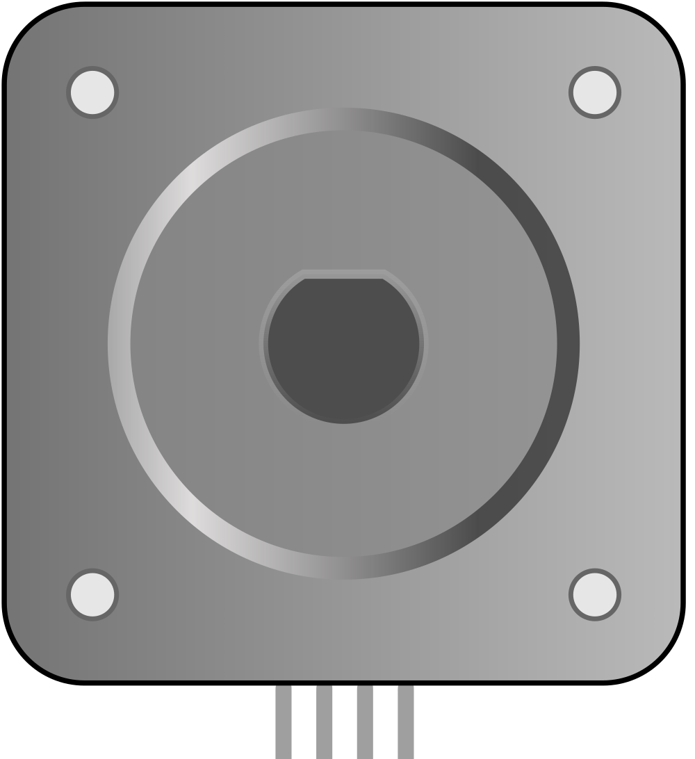
The Bipolar Stepper Motor (NEMA 17) is a type of electric motor that divides a full rotation into a large number of discrete steps. This allows for precise control of position, speed, and acceleration, making it ideal for applications requiring high accuracy. The "NEMA 17" designation refers to the motor's faceplate dimensions, which measure 1.7 x 1.7 inches (43.2 x 43.2 mm). This motor is widely used in 3D printers, CNC machines, robotics, and other motion control systems due to its compact size and reliable performance.
Explore Projects Built with Bipolar Stepper Motor (NEMA 17)
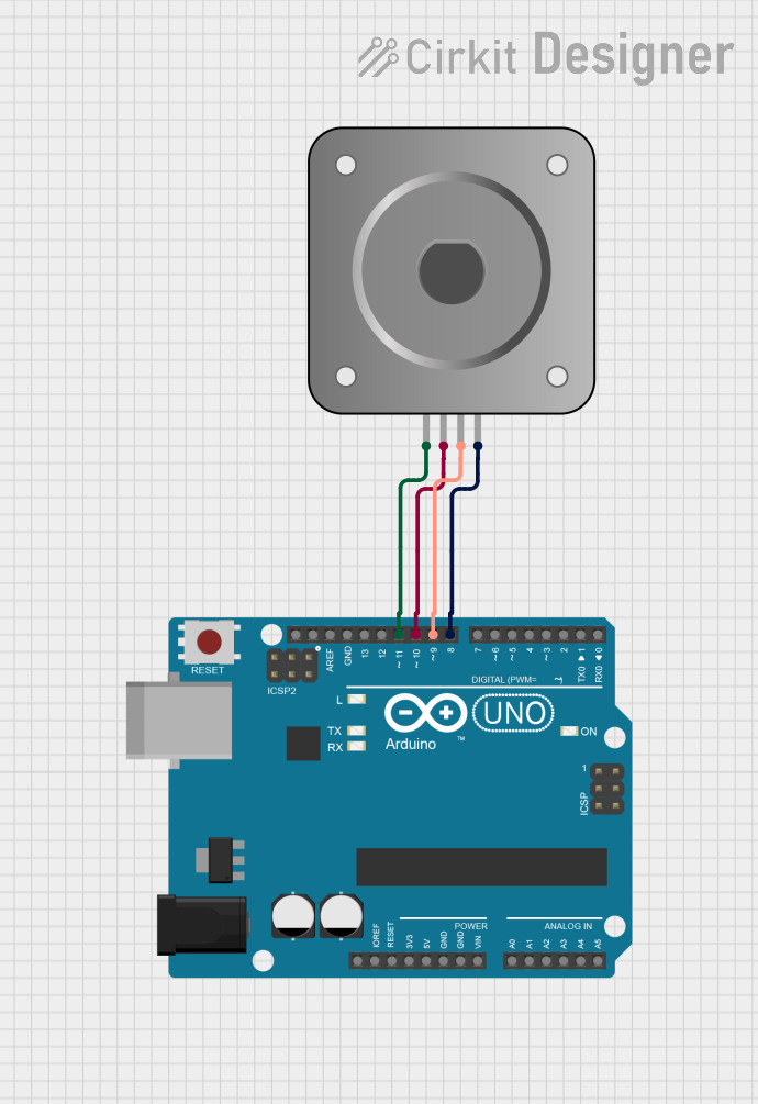
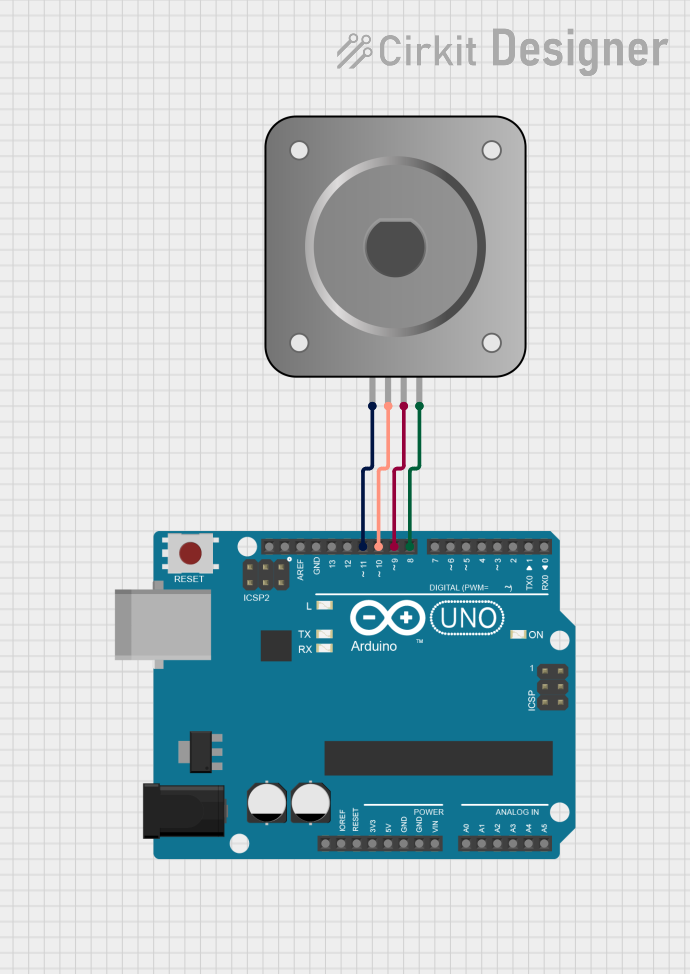
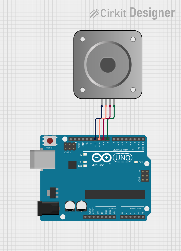
Explore Projects Built with Bipolar Stepper Motor (NEMA 17)
Common Applications:
- 3D printers for precise layer positioning
- CNC machines for accurate cutting and milling
- Robotics for controlled movement
- Camera sliders and gimbals
- Automated conveyor systems
Technical Specifications
Below are the key technical details for a typical NEMA 17 bipolar stepper motor. Note that specific models may vary slightly, so always refer to the datasheet for your motor.
General Specifications:
- Step Angle: 1.8° (200 steps per revolution)
- Holding Torque: 40-50 N·cm (varies by model)
- Rated Voltage: 2.8V (typical)
- Rated Current: 1.2A per phase
- Resistance: 2.4Ω per phase
- Inductance: 3.2 mH per phase
- Shaft Diameter: 5 mm
- Body Length: 38-48 mm (varies by model)
- Weight: ~280 g
Pin Configuration and Descriptions:
The NEMA 17 bipolar stepper motor has four wires, corresponding to two coils (phases). The table below describes the typical wire colors and their connections:
| Pin/Wire Color | Description | Function |
|---|---|---|
| Red | Coil A (positive) | Connect to driver output A+ |
| Blue | Coil A (negative) | Connect to driver output A- |
| Green | Coil B (positive) | Connect to driver output B+ |
| Black | Coil B (negative) | Connect to driver output B- |
Note: Wire colors may vary depending on the manufacturer. Use a multimeter to verify coil pairs by checking continuity.
Usage Instructions
How to Use the NEMA 17 in a Circuit:
Connect to a Stepper Motor Driver:
The NEMA 17 requires a stepper motor driver (e.g., A4988 or DRV8825) to control its movement. The driver translates step and direction signals from a microcontroller into precise coil energization patterns.Power Requirements:
Ensure the power supply matches the voltage and current requirements of the motor and driver. For example, a 12V or 24V power supply is commonly used with stepper motor drivers.Microcontroller Interface:
Connect the stepper motor driver to a microcontroller (e.g., Arduino UNO). The driver typically has pins for:- Step: Receives pulses to move the motor one step per pulse.
- Direction: Sets the rotation direction (clockwise or counterclockwise).
- Enable: Activates or deactivates the motor.
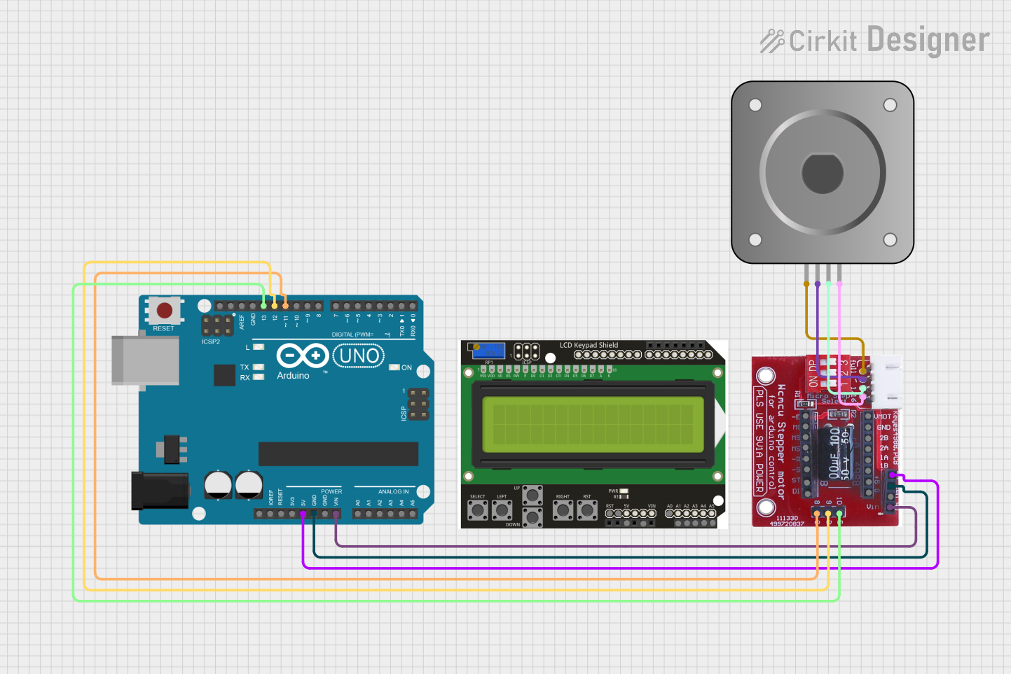
Wiring Example:
- Connect the motor wires to the driver outputs (A+, A-, B+, B-).
- Connect the driver's step, direction, and enable pins to the microcontroller's digital pins.
- Provide power to the driver and motor.
Arduino UNO Example Code:
Below is an example of how to control a NEMA 17 stepper motor using an Arduino UNO and an A4988 driver.
// Define pin connections
#define STEP_PIN 3       // Pin for step signal
#define DIR_PIN 4        // Pin for direction signal
#define ENABLE_PIN 5     // Pin to enable/disable the motor

void setup() {
  pinMode(STEP_PIN, OUTPUT);   // Set step pin as output
  pinMode(DIR_PIN, OUTPUT);    // Set direction pin as output
  pinMode(ENABLE_PIN, OUTPUT); // Set enable pin as output

  digitalWrite(ENABLE_PIN, LOW); // Enable the motor
}

void loop() {
  digitalWrite(DIR_PIN, HIGH); // Set direction to clockwise

  // Rotate motor 200 steps (1 full revolution for 1.8° step angle)
  for (int i = 0; i < 200; i++) {
    digitalWrite(STEP_PIN, HIGH); // Generate step pulse
    delayMicroseconds(1000);      // Wait 1 ms
    digitalWrite(STEP_PIN, LOW);  // End step pulse
    delayMicroseconds(1000);      // Wait 1 ms
  }

  delay(1000); // Wait 1 second before changing direction

  digitalWrite(DIR_PIN, LOW); // Set direction to counterclockwise

  // Rotate motor 200 steps in the opposite direction
  for (int i = 0; i < 200; i++) {
    digitalWrite(STEP_PIN, HIGH);
    delayMicroseconds(1000);
    digitalWrite(STEP_PIN, LOW);
    delayMicroseconds(1000);
  }

  delay(1000); // Wait 1 second before repeating
}
Important Considerations:
- Current Limiting: Adjust the current limit on the stepper driver to match the motor's rated current. This prevents overheating and damage.
- Microstepping: Enable microstepping on the driver for smoother motion and reduced noise.
- Cooling: Use a heatsink or fan for the driver if it gets too hot during operation.
- Backlash: Minimize mechanical backlash in your system for better accuracy.
Troubleshooting and FAQs
Common Issues and Solutions:
Motor Not Moving:
- Cause: Incorrect wiring or loose connections.
- Solution: Double-check the wiring and ensure all connections are secure.
Motor Vibrates but Doesn't Rotate:
- Cause: Incorrect coil pairing.
- Solution: Verify coil pairs using a multimeter and rewire accordingly.
Driver Overheating:
- Cause: Current limit set too high.
- Solution: Adjust the current limit on the driver to match the motor's rated current.
Skipping Steps:
- Cause: Insufficient torque or excessive load.
- Solution: Reduce the load or increase the motor's current (within safe limits).
Noisy Operation:
- Cause: Full-step mode or mechanical resonance.
- Solution: Enable microstepping on the driver and ensure the motor is securely mounted.
FAQs:
Q: Can I run the NEMA 17 directly from an Arduino?
A: No, the Arduino cannot supply the required current. Always use a stepper motor driver.Q: How do I identify coil pairs if wire colors are different?
A: Use a multimeter to check continuity. Wires with continuity belong to the same coil.Q: Can I use a higher voltage power supply?
A: Yes, but ensure the stepper driver supports the voltage and adjust the current limit accordingly.
By following this documentation, you can effectively use the NEMA 17 stepper motor in your projects with confidence and precision.