
How to Use ESP-01 Adapter Module 3.3-5V: Examples, Pinouts, and Specs
 Design with ESP-01 Adapter Module 3.3-5V in Cirkit Designer
Introduction
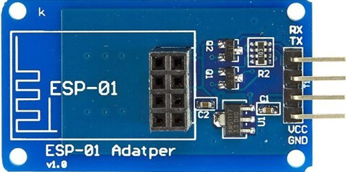
The ESP-01 Adapter Module 3.3-5V is a compact and essential accessory designed to facilitate the use of the ESP-01 Wi-Fi module with 5V systems. It acts as a voltage regulator and level shifter, converting 5V signals to 3.3V, which is required by the ESP-01 module. This adapter ensures safe and reliable operation of the ESP-01 module when interfaced with microcontrollers or other devices operating at 5V logic levels.
Explore Projects Built with ESP-01 Adapter Module 3.3-5V
 Open Project in Cirkit Designer
 Open Project in Cirkit Designer
 Open Project in Cirkit Designer
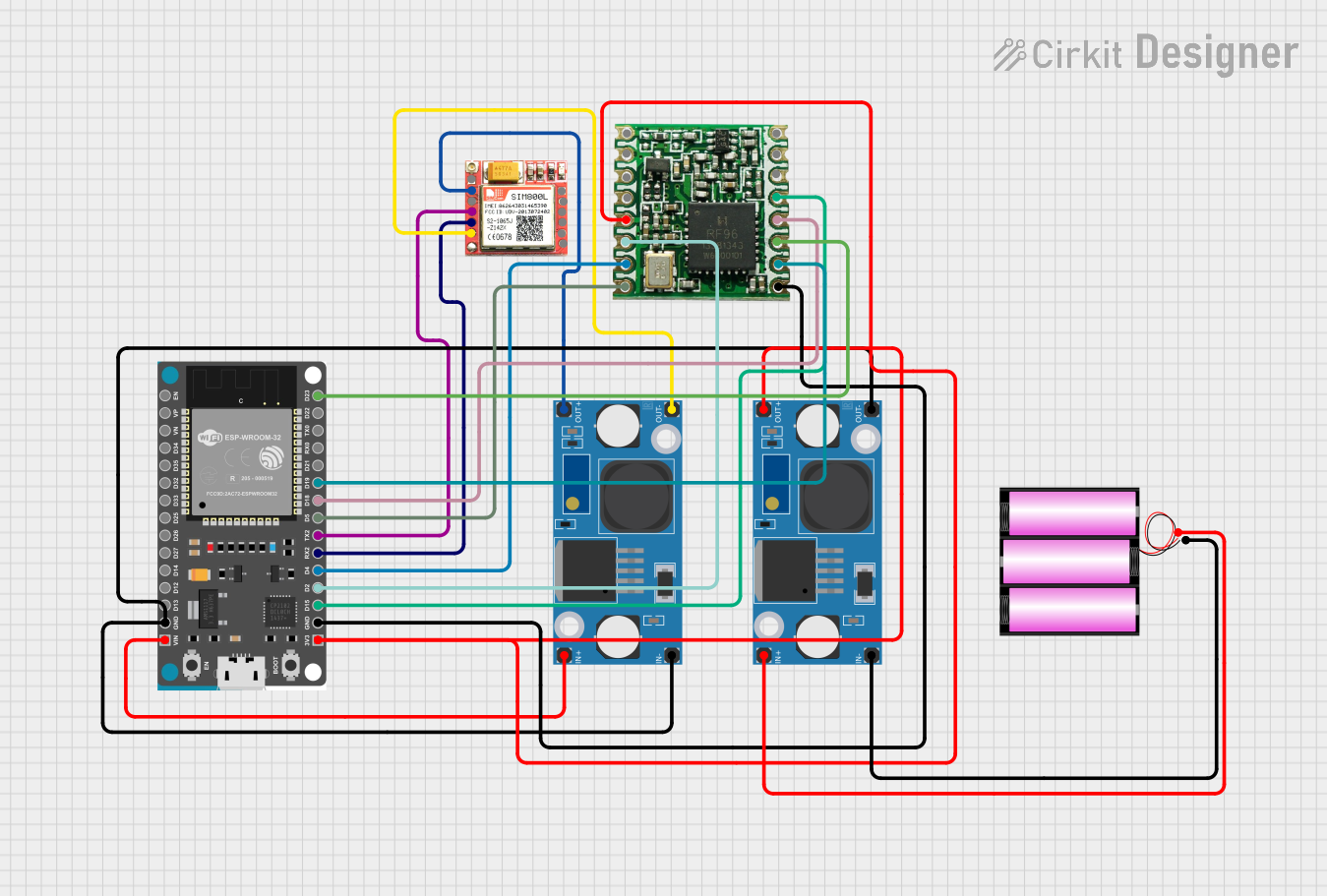 Open Project in Cirkit Designer
Explore Projects Built with ESP-01 Adapter Module 3.3-5V
Open Project in Cirkit DesignerOpen Project in Cirkit DesignerOpen Project in Cirkit DesignerOpen Project in Cirkit DesignerCommon Applications and Use Cases
- IoT Projects: Enables seamless integration of the ESP-01 module into IoT systems.
- Microcontroller Interfacing: Allows the ESP-01 to communicate with 5V microcontrollers like Arduino UNO.
- Prototyping: Simplifies the process of testing and developing Wi-Fi-enabled projects.
- Home Automation: Used in smart home devices for wireless communication.
Technical Specifications
The ESP-01 Adapter Module is designed to provide a stable and safe interface for the ESP-01 Wi-Fi module. Below are its key specifications:
Key Technical Details
| Parameter | Specification |
|---|---|
| Input Voltage | 5V |
| Output Voltage | 3.3V |
| Maximum Current Output | 500mA |
| Dimensions | 25mm x 15mm x 10mm |
| Operating Temperature | -40°C to 85°C |
| Compatibility | ESP-01 Wi-Fi Module |
Pin Configuration and Descriptions
The ESP-01 Adapter Module has a simple pinout for easy integration. Below is the pin configuration:
| Pin Name | Description |
|---|---|
| VCC | Connect to 5V power supply |
| GND | Ground connection |
| TX | Transmit pin (connects to RX of microcontroller) |
| RX | Receive pin (connects to TX of microcontroller) |
Usage Instructions
How to Use the ESP-01 Adapter Module in a Circuit
Powering the Module:
- Connect the
VCCpin of the adapter to a 5V power source. - Connect the
GNDpin to the ground of your circuit.
- Connect the
Connecting to a Microcontroller:
- Connect the
TXpin of the adapter to theRXpin of your microcontroller. - Connect the
RXpin of the adapter to theTXpin of your microcontroller.
- Connect the
Mounting the ESP-01 Module:
- Insert the ESP-01 module into the adapter's socket, ensuring proper alignment of pins.
Programming the ESP-01:
- Use an FTDI programmer or a microcontroller to upload code to the ESP-01 module.
- Ensure the adapter is powered during the programming process.
Important Considerations and Best Practices
- Voltage Compatibility: Do not connect the ESP-01 module directly to a 5V system without the adapter, as it may damage the module.
- Power Supply: Use a stable 5V power source to avoid fluctuations that could affect the ESP-01's performance.
- Pin Alignment: Double-check the alignment of the ESP-01 module when inserting it into the adapter to prevent damage.
- Baud Rate: Ensure the baud rate of the ESP-01 matches the settings of your microcontroller for proper communication.
Example: Connecting to an Arduino UNO
Below is an example of how to use the ESP-01 Adapter Module with an Arduino UNO:
Circuit Connections
VCC→ Arduino5VGND→ ArduinoGNDTX→ ArduinoRX(Pin 0)RX→ ArduinoTX(Pin 1)
Sample Code
#include <SoftwareSerial.h>

// Define RX and TX pins for SoftwareSerial
SoftwareSerial espSerial(2, 3); // RX = Pin 2, TX = Pin 3

void setup() {
  Serial.begin(9600); // Initialize Serial Monitor at 9600 baud
  espSerial.begin(9600); // Initialize ESP-01 communication at 9600 baud

  Serial.println("ESP-01 Adapter Module Test");
  espSerial.println("AT"); // Send AT command to ESP-01
}

void loop() {
  // Check if data is available from ESP-01
  if (espSerial.available()) {
    String response = espSerial.readString();
    Serial.println("ESP-01 Response: " + response);
  }

  // Check if data is available from Serial Monitor
  if (Serial.available()) {
    String command = Serial.readString();
    espSerial.println(command); // Send command to ESP-01
  }
}
Notes:
- Use
SoftwareSerialto avoid conflicts with the Arduino's hardware serial pins. - Ensure the ESP-01 module is in AT command mode for the above example.
Troubleshooting and FAQs
Common Issues and Solutions
ESP-01 Not Responding to Commands:
- Cause: Incorrect baud rate or wiring.
- Solution: Verify the baud rate (default is 9600) and check the TX/RX connections.
Module Overheating:
- Cause: Incorrect voltage supply.
- Solution: Ensure the adapter is powered with 5V and not higher.
No Communication Between ESP-01 and Microcontroller:
- Cause: Misaligned pins or loose connections.
- Solution: Recheck the alignment of the ESP-01 module in the adapter and secure all connections.
ESP-01 Not Entering Programming Mode:
- Cause: GPIO0 not grounded during programming.
- Solution: Ensure GPIO0 is connected to GND when uploading code.
FAQs
Q1: Can I use the ESP-01 Adapter Module with a 3.3V system?
A1: No, the adapter is designed for 5V systems. If your system operates at 3.3V, you can connect the ESP-01 module directly without the adapter.
Q2: What is the maximum current the adapter can supply to the ESP-01?
A2: The adapter can supply up to 500mA, which is sufficient for the ESP-01 module.
Q3: Can I use the adapter for other 3.3V modules?
A3: While the adapter is specifically designed for the ESP-01, it may work with other 3.3V modules, but compatibility is not guaranteed.
Q4: Why is my ESP-01 not connecting to Wi-Fi?
A4: Ensure the correct SSID and password are configured in your code. Also, check the signal strength of your Wi-Fi network.
By following this documentation, you can effectively use the ESP-01 Adapter Module 3.3-5V in your projects and troubleshoot common issues with ease.