How to Use Sparkfun Odometry Sensor: Examples, Pinouts, and Specs
Introduction
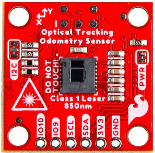
The Sparkfun Odometry Sensor (Part ID: Qwiic) is a compact and versatile sensor designed to measure the distance traveled by a robot or vehicle. It provides precise feedback for navigation and movement control, making it an essential component for robotics, automation, and other motion-based applications. The sensor integrates seamlessly with Sparkfun's Qwiic ecosystem, enabling easy connection and communication via I2C.
Explore Projects Built with Sparkfun Odometry Sensor


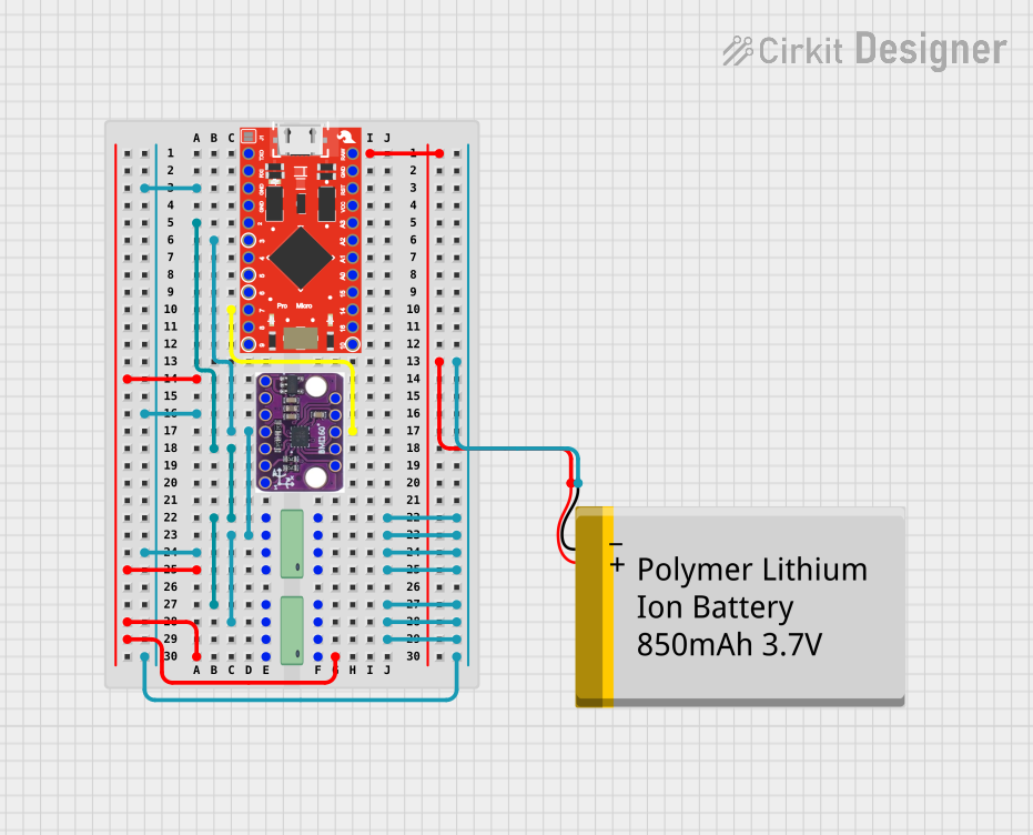
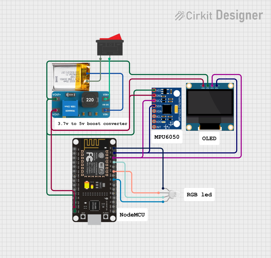
Explore Projects Built with Sparkfun Odometry Sensor
Common Applications and Use Cases
- Robotics navigation and path planning
- Autonomous vehicle movement tracking
- Distance measurement for conveyor belts or moving platforms
- Feedback control in motorized systems
- Educational and research projects in robotics and automation
Technical Specifications
The Sparkfun Odometry Sensor is designed for high accuracy and ease of use. Below are its key technical details:
| Parameter | Specification |
|---|---|
| Supply Voltage | 3.3V |
| Communication Protocol | I2C (Qwiic-compatible) |
| I2C Address (Default) | 0x40 |
| Measurement Range | 0 to 10,000 revolutions (configurable) |
| Resolution | 0.1 mm (depends on wheel size) |
| Operating Temperature | -40°C to +85°C |
| Dimensions | 25.4mm x 25.4mm (1" x 1") |
Pin Configuration and Descriptions
The Sparkfun Odometry Sensor uses a Qwiic connector for I2C communication. For custom wiring, the pinout is as follows:
| Pin | Name | Description |
|---|---|---|
| 1 | GND | Ground (0V reference) |
| 2 | 3.3V | Power supply (3.3V input) |
| 3 | SDA | I2C Data Line |
| 4 | SCL | I2C Clock Line |
Usage Instructions
How to Use the Component in a Circuit
- Connect the Sensor: Use a Qwiic cable to connect the sensor to a Qwiic-enabled microcontroller, such as an Arduino UNO with a Qwiic Shield. Alternatively, wire the sensor manually using the pinout table above.
- Power the Sensor: Ensure the sensor is powered with 3.3V. Do not exceed this voltage to avoid damage.
- Establish I2C Communication: Configure your microcontroller to communicate with the sensor using the I2C protocol. The default I2C address is
0x40. - Read Data: Use the appropriate library or I2C commands to read odometry data, such as distance traveled or wheel revolutions.
Important Considerations and Best Practices
- Wheel Size Calibration: Ensure the sensor is calibrated for the specific wheel size of your robot or vehicle. This ensures accurate distance measurements.
- Avoid Noise: Place the sensor away from sources of electrical noise, such as motors or high-current wires, to maintain reliable readings.
- Secure Mounting: Mount the sensor securely to prevent vibrations or misalignment, which can affect accuracy.
- Check I2C Address Conflicts: If multiple I2C devices are connected, ensure no address conflicts. The sensor's address can be changed if needed.
Example Code for Arduino UNO
Below is an example of how to use the Sparkfun Odometry Sensor with an Arduino UNO:
#include <Wire.h>

// Default I2C address for the Sparkfun Odometry Sensor
#define ODOMETRY_SENSOR_ADDR 0x40

void setup() {
  Wire.begin(); // Initialize I2C communication
  Serial.begin(9600); // Start serial communication for debugging

  // Check if the sensor is connected
  Wire.beginTransmission(ODOMETRY_SENSOR_ADDR);
  if (Wire.endTransmission() == 0) {
    Serial.println("Odometry Sensor connected!");
  } else {
    Serial.println("Error: Odometry Sensor not detected.");
  }
}

void loop() {
  // Request 4 bytes of data from the sensor (example: distance in mm)
  Wire.beginTransmission(ODOMETRY_SENSOR_ADDR);
  Wire.write(0x00); // Command to read distance (check sensor datasheet)
  Wire.endTransmission();

  Wire.requestFrom(ODOMETRY_SENSOR_ADDR, 4);
  if (Wire.available() == 4) {
    uint32_t distance = 0;
    for (int i = 0; i < 4; i++) {
      distance |= (Wire.read() << (8 * i)); // Combine bytes into a 32-bit value
    }
    Serial.print("Distance: ");
    Serial.print(distance);
    Serial.println(" mm");
  } else {
    Serial.println("Error: Failed to read data.");
  }

  delay(1000); // Wait 1 second before the next reading
}
Troubleshooting and FAQs
Common Issues and Solutions
Sensor Not Detected
- Cause: Incorrect wiring or I2C address conflict.
- Solution: Double-check the wiring and ensure the correct I2C address is used. Use an I2C scanner sketch to detect connected devices.
Inaccurate Distance Measurements
- Cause: Incorrect wheel size calibration or sensor misalignment.
- Solution: Verify the wheel size configuration and ensure the sensor is mounted securely.
No Data Output
- Cause: Faulty Qwiic cable or incorrect I2C commands.
- Solution: Test the Qwiic cable for continuity and refer to the sensor's datasheet for proper I2C commands.
FAQs
Q: Can the sensor work with 5V systems?
A: No, the sensor operates at 3.3V. Use a level shifter if connecting to a 5V system.
Q: How do I change the I2C address?
A: Refer to the sensor's datasheet for instructions on modifying the I2C address via software or hardware configuration.
Q: Is the sensor compatible with Raspberry Pi?
A: Yes, the sensor can be used with Raspberry Pi via the I2C interface. Ensure proper voltage levels are maintained.
Q: What is the maximum distance the sensor can measure?
A: The sensor can measure up to 10,000 revolutions, but the actual distance depends on the wheel size.
By following this documentation, users can effectively integrate the Sparkfun Odometry Sensor into their projects for accurate distance measurement and navigation.