How to Use Generic PMW3901 Module: Examples, Pinouts, and Specs
Introduction
The Generic PMW3901 Module is a motion sensor module that leverages the PMW3901 optical flow sensor to detect movement and track motion. This module is widely used in applications requiring precise motion tracking, such as robotics, drones, and autonomous vehicles. By analyzing the optical flow of surfaces beneath it, the PMW3901 can measure relative motion, making it an essential component for navigation and stabilization systems.
Explore Projects Built with Generic PMW3901 Module


Explore Projects Built with Generic PMW3901 Module
Common Applications
- Drones: Used for position hold and stabilization in GPS-denied environments.
- Robotics: Enables precise navigation and obstacle avoidance.
- Gaming and VR: Tracks motion for immersive experiences.
- Industrial Automation: Monitors conveyor belt movement or robotic arm positioning.
Technical Specifications
The following table outlines the key technical details of the Generic PMW3901 Module:
| Parameter | Value |
|---|---|
| Sensor Type | Optical Flow |
| Operating Voltage | 3.3V |
| Communication Protocol | SPI |
| Maximum Frame Rate | 200 fps |
| Field of View (FOV) | 42° x 42° |
| Operating Temperature | -20°C to 85°C |
| Dimensions | 25mm x 25mm x 5mm |
Pin Configuration
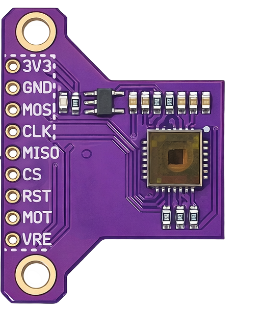
The PMW3901 module typically has the following pinout:
| Pin | Name | Description |
|---|---|---|
| 1 | VCC | Power supply (3.3V) |
| 2 | GND | Ground |
| 3 | MISO | Master In Slave Out (SPI data output) |
| 4 | MOSI | Master Out Slave In (SPI data input) |
| 5 | SCK | Serial Clock (SPI clock signal) |
| 6 | CS | Chip Select (active low, used to enable the module) |
| 7 | INT | Interrupt pin (optional, for motion detection alerts) |
Usage Instructions
Connecting the PMW3901 Module
- Power Supply: Connect the
VCCpin to a 3.3V power source and theGNDpin to ground. - SPI Communication: Connect the
MISO,MOSI,SCK, andCSpins to the corresponding SPI pins on your microcontroller or development board. - Interrupt Pin (Optional): If your application requires motion detection alerts, connect the
INTpin to a GPIO pin on your microcontroller.
Example: Using the PMW3901 with Arduino UNO
The PMW3901 module can be interfaced with an Arduino UNO using an SPI library. Below is an example code snippet to initialize and read motion data from the module:
#include <SPI.h>

// Define SPI pins for the PMW3901 module
#define CS_PIN 10  // Chip Select pin
#define SCK_PIN 13 // Serial Clock pin
#define MOSI_PIN 11 // Master Out Slave In pin
#define MISO_PIN 12 // Master In Slave Out pin

// Function to initialize the PMW3901 module
void setupPMW3901() {
  pinMode(CS_PIN, OUTPUT); // Set CS pin as output
  digitalWrite(CS_PIN, HIGH); // Set CS pin high (inactive)
  SPI.begin(); // Initialize SPI communication
  Serial.begin(9600); // Start serial communication for debugging
  Serial.println("PMW3901 Initialization Complete");
}

// Function to read motion data from the PMW3901
void readMotionData() {
  digitalWrite(CS_PIN, LOW); // Activate the module by pulling CS low
  delayMicroseconds(10); // Small delay for stability

  // Example: Send a command to read motion data (replace with actual command)
  byte motionData = SPI.transfer(0x00); // Replace 0x00 with the actual register address
  digitalWrite(CS_PIN, HIGH); // Deactivate the module by pulling CS high

  // Print the motion data to the serial monitor
  Serial.print("Motion Data: ");
  Serial.println(motionData);
}

void setup() {
  setupPMW3901(); // Initialize the PMW3901 module
}

void loop() {
  readMotionData(); // Continuously read motion data
  delay(100); // Delay to avoid overwhelming the serial monitor
}
Important Considerations
- Voltage Levels: Ensure the module is powered with 3.3V. Using 5V may damage the sensor.
- SPI Configuration: Verify that the SPI settings (clock speed, mode, etc.) match the module's requirements.
- Surface Texture: The PMW3901 performs best on textured surfaces. Smooth or reflective surfaces may reduce accuracy.
Troubleshooting and FAQs
Common Issues
No Motion Data Detected
- Cause: Incorrect SPI wiring or configuration.
- Solution: Double-check the connections and ensure the SPI settings match the module's requirements.
Inconsistent Motion Readings
- Cause: The module is placed too far from or too close to the surface.
- Solution: Maintain an optimal distance of 80mm to 120mm from the surface.
Module Not Responding
- Cause: Incorrect power supply voltage.
- Solution: Ensure the module is powered with 3.3V.
FAQs
Q: Can the PMW3901 module be used outdoors?
A: Yes, but its performance may be affected by bright sunlight or reflective surfaces.Q: What is the maximum speed the module can track?
A: The PMW3901 can track motion up to 7.4 meters per second.Q: Can I use the PMW3901 with a 5V microcontroller?
A: Yes, but you must use a level shifter to convert the 5V logic to 3.3V for the SPI pins.
This documentation provides a comprehensive guide to using the Generic PMW3901 Module effectively. For further assistance, consult the module's datasheet or community forums.