
How to Use MMA8452Q: Examples, Pinouts, and Specs
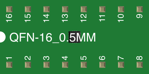
 Design with MMA8452Q in Cirkit Designer
Introduction
The MMA8452Q is a low-power, 3-axis accelerometer designed for motion sensing applications. It provides a digital output via I2C or SPI interfaces, making it easy to integrate into a wide range of electronic systems. With selectable sensitivity ranges of ±2g, ±4g, and ±8g, the MMA8452Q is ideal for detecting motion, orientation, and free-fall events. Its compact size and low power consumption make it a popular choice for smartphones, tablets, wearable devices, and gaming peripherals.
Explore Projects Built with MMA8452Q
 Open Project in Cirkit Designer
 Open Project in Cirkit Designer
 Open Project in Cirkit Designer
 Open Project in Cirkit Designer
Explore Projects Built with MMA8452Q
Open Project in Cirkit DesignerOpen Project in Cirkit DesignerOpen Project in Cirkit DesignerOpen Project in Cirkit DesignerCommon Applications
- Motion detection in smartphones and tablets
- Orientation sensing in wearable devices
- Free-fall detection for device protection
- Gaming controllers and peripherals
- Step counting and activity monitoring
Technical Specifications
The MMA8452Q offers a variety of features and specifications that make it versatile for motion sensing applications.
Key Specifications
| Parameter | Value |
|---|---|
| Operating Voltage | 1.95V to 3.6V |
| Communication Interface | I2C (up to 400 kHz), SPI |
| Measurement Range | ±2g, ±4g, ±8g (selectable) |
| Output Data Rate (ODR) | 1.56 Hz to 800 Hz |
| Resolution | 12-bit |
| Operating Temperature | -40°C to +85°C |
| Power Consumption | 6 µA (low-power mode) |
| Package | 3 mm x 3 mm x 1 mm, 16-pin QFN |
Pin Configuration and Descriptions
The MMA8452Q is housed in a 16-pin QFN package. Below is the pin configuration:
| Pin Number | Pin Name | Description |
|---|---|---|
| 1 | VDD | Power supply (1.95V to 3.6V) |
| 2 | VSS | Ground |
| 3 | SDA | I2C data line |
| 4 | SCL | I2C clock line |
| 5 | INT1 | Interrupt 1 output |
| 6 | INT2 | Interrupt 2 output |
| 7 | NC | No connection |
| 8 | NC | No connection |
| 9 | NC | No connection |
| 10 | NC | No connection |
| 11 | NC | No connection |
| 12 | NC | No connection |
| 13 | NC | No connection |
| 14 | NC | No connection |
| 15 | NC | No connection |
| 16 | NC | No connection |
Note: Pins labeled as "NC" should not be connected to any circuit.
Usage Instructions
The MMA8452Q can be easily integrated into a circuit using its I2C or SPI interface. Below are the steps and considerations for using the component effectively.
Connecting the MMA8452Q to an Arduino UNO
- Power Supply: Connect the VDD pin to the 3.3V output of the Arduino UNO and the VSS pin to GND.
- I2C Interface: Connect the SDA pin to the Arduino's A4 pin and the SCL pin to the A5 pin.
- Interrupts (Optional): Connect INT1 and/or INT2 to any digital input pins on the Arduino if you want to use interrupt-driven events.
- Pull-Up Resistors: Use 4.7kΩ pull-up resistors on the SDA and SCL lines if not already present on your board.
Sample Arduino Code
The following code demonstrates how to initialize the MMA8452Q and read acceleration data via I2C.
#include <Wire.h>

#define MMA8452Q_ADDRESS 0x1D // Default I2C address for MMA8452Q

void setup() {
  Wire.begin(); // Initialize I2C communication
  Serial.begin(9600); // Initialize serial communication for debugging

  // Initialize MMA8452Q
  Wire.beginTransmission(MMA8452Q_ADDRESS);
  Wire.write(0x2A); // CTRL_REG1 register
  Wire.write(0x01); // Set active mode
  Wire.endTransmission();

  Serial.println("MMA8452Q initialized.");
}

void loop() {
  int16_t x, y, z;

  // Request 6 bytes of acceleration data from the MMA8452Q
  Wire.beginTransmission(MMA8452Q_ADDRESS);
  Wire.write(0x01); // Start reading from OUT_X_MSB register
  Wire.endTransmission(false);
  Wire.requestFrom(MMA8452Q_ADDRESS, 6);

  if (Wire.available() == 6) {
    x = (Wire.read() << 8) | Wire.read(); // Combine MSB and LSB for X-axis
    y = (Wire.read() << 8) | Wire.read(); // Combine MSB and LSB for Y-axis
    z = (Wire.read() << 8) | Wire.read(); // Combine MSB and LSB for Z-axis

    // Print acceleration values
    Serial.print("X: ");
    Serial.print(x);
    Serial.print(" Y: ");
    Serial.print(y);
    Serial.print(" Z: ");
    Serial.println(z);
  }

  delay(100); // Delay for readability
}
Best Practices
- Ensure the MMA8452Q is powered within its specified voltage range (1.95V to 3.6V).
- Use appropriate pull-up resistors on the I2C lines if not already present.
- Configure the sensitivity range (±2g, ±4g, or ±8g) based on your application requirements.
- Avoid exposing the component to extreme temperatures or mechanical stress.
Troubleshooting and FAQs
Common Issues
No Communication with the Device:
- Ensure the I2C address (default: 0x1D) matches the one in your code.
- Check the connections for SDA and SCL lines.
- Verify that pull-up resistors are present on the I2C lines.
Incorrect or No Acceleration Data:
- Confirm that the MMA8452Q is in active mode by checking the CTRL_REG1 register.
- Ensure the sensitivity range is configured correctly for your application.
Interrupts Not Triggering:
- Verify that the interrupt pins (INT1/INT2) are connected to the correct Arduino pins.
- Check the interrupt configuration registers in the MMA8452Q.
FAQs
Q: Can the MMA8452Q operate at 5V?
A: No, the MMA8452Q operates within a voltage range of 1.95V to 3.6V. Use a voltage regulator if your system operates at 5V.
Q: How do I change the sensitivity range?
A: The sensitivity range can be configured by writing to the XYZ_DATA_CFG register. Refer to the datasheet for details.
Q: Is the MMA8452Q compatible with SPI?
A: Yes, the MMA8452Q supports both I2C and SPI interfaces. However, this documentation focuses on I2C usage.
Q: What is the default I2C address of the MMA8452Q?
A: The default I2C address is 0x1D.