How to Use I2S mic: Examples, Pinouts, and Specs
Introduction
The INMP441ACEZ-R0 is a high-performance, low-power, digital microphone manufactured by TDK InvenSense. It utilizes the I2S (Inter-IC Sound) protocol to transmit audio data in a digital format, eliminating the need for analog-to-digital conversion and reducing noise and interference. This makes it an ideal choice for applications requiring high-quality audio capture.
Explore Projects Built with I2S mic
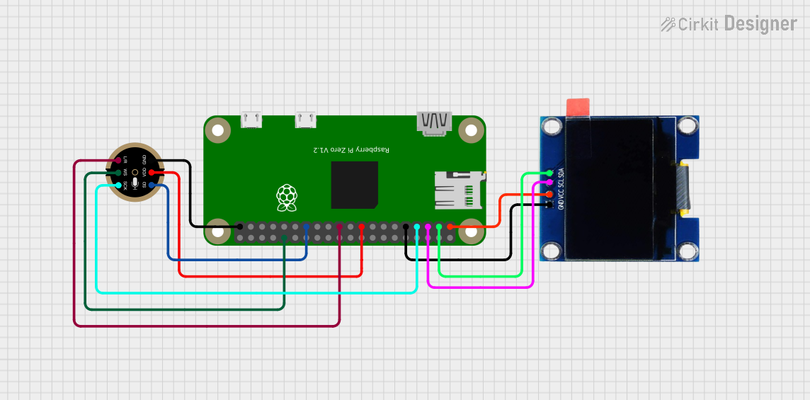
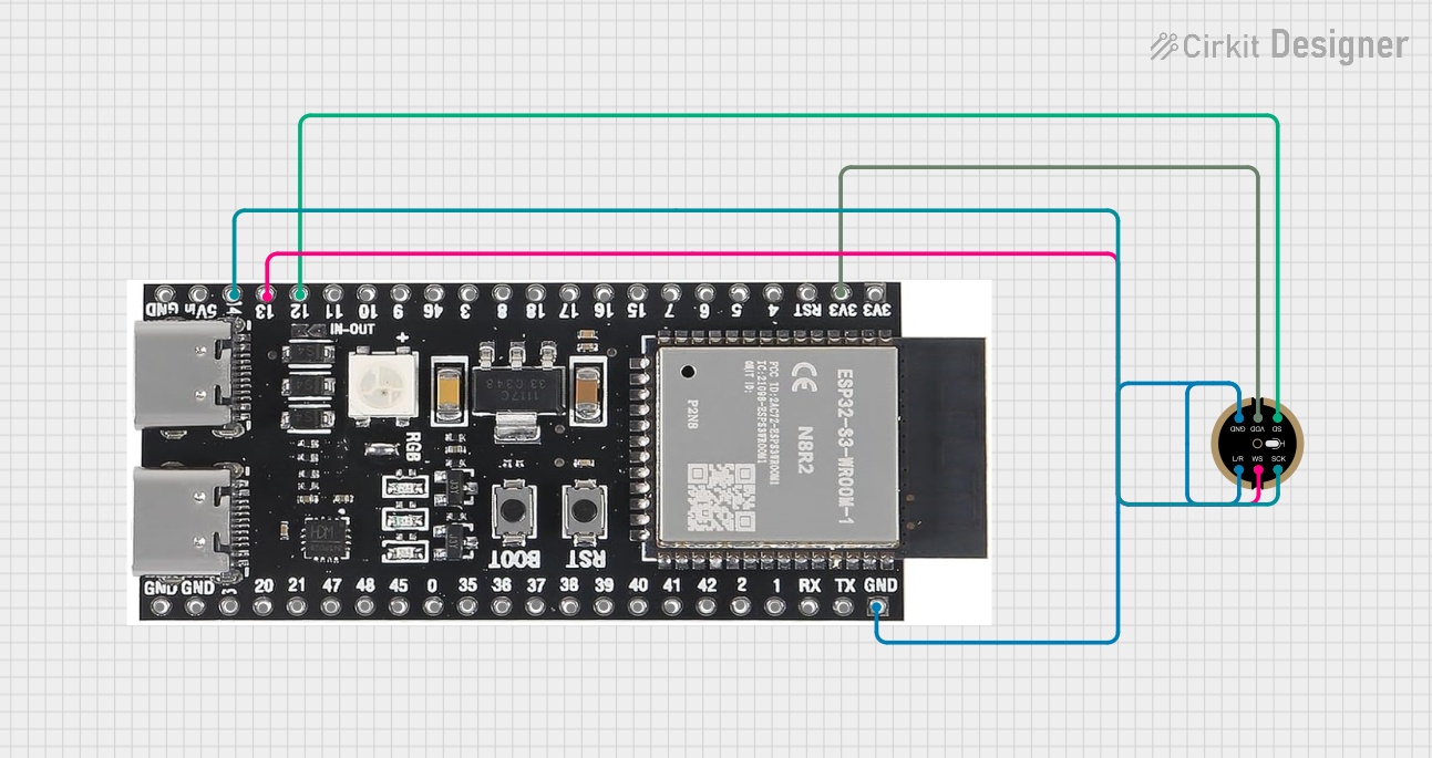
Explore Projects Built with I2S mic
Common Applications
- Voice recognition systems
- Smart home devices (e.g., smart speakers, IoT devices)
- Audio recording and streaming
- Noise-canceling systems
- Wearable devices
Technical Specifications
The following table outlines the key technical details of the INMP441ACEZ-R0:
| Parameter | Value |
|---|---|
| Supply Voltage (VDD) | 1.8V to 3.3V |
| Current Consumption | 1.4 mA (typical) |
| Signal-to-Noise Ratio (SNR) | 61 dB |
| Acoustic Overload Point | 120 dB SPL |
| Frequency Response | 60 Hz to 15 kHz |
| Output Format | I2S (24-bit, 2's complement) |
| Sensitivity | -26 dBFS ±1 dB |
| Operating Temperature | -40°C to +85°C |
| Package Dimensions | 3.5 mm × 2.65 mm × 0.98 mm |
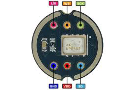
Pin Configuration and Descriptions
The INMP441ACEZ-R0 has a 5-pin configuration. The table below describes each pin:
| Pin Name | Pin Number | Description |
|---|---|---|
| VDD | 1 | Power supply input (1.8V to 3.3V). |
| GND | 2 | Ground connection. |
| WS | 3 | Word Select (I2S clock signal for left/right channel selection). |
| SCK | 4 | Serial Clock (I2S clock signal for data synchronization). |
| SD | 5 | Serial Data (I2S data output). Carries the digital audio signal. |
Usage Instructions
How to Use the INMP441ACEZ-R0 in a Circuit
- Power Supply: Connect the VDD pin to a regulated power supply (1.8V to 3.3V) and the GND pin to the ground.
- I2S Interface: Connect the WS, SCK, and SD pins to the corresponding I2S pins on your microcontroller or audio processor.
- Bypass Capacitor: Place a 0.1 µF ceramic capacitor close to the VDD pin to stabilize the power supply.
- Microcontroller Configuration: Configure your microcontroller to operate in I2S mode with a compatible clock frequency and data format (24-bit, 2's complement).
Important Considerations
- Ensure the I2S clock signals (SCK and WS) are stable and within the microphone's operating range.
- Avoid placing the microphone near high-frequency noise sources to minimize interference.
- Use proper PCB layout techniques to ensure clean signal transmission.
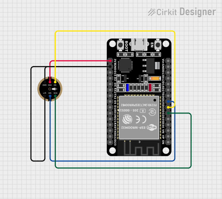
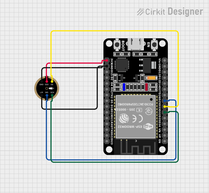
Example: Connecting the INMP441ACEZ-R0 to an Arduino UNO
The Arduino UNO does not have native I2S support, but you can use an external I2S interface module or a microcontroller like the ESP32, which supports I2S natively. Below is an example code snippet for using the INMP441ACEZ-R0 with an ESP32:
#include <driver/i2s.h>

// I2S configuration
#define I2S_NUM         I2S_NUM_0  // I2S port number
#define I2S_WS_PIN      25         // Word Select pin (WS)
#define I2S_SCK_PIN     26         // Serial Clock pin (SCK)
#define I2S_SD_PIN      22         // Serial Data pin (SD)

void setup() {
  // Configure I2S
  i2s_config_t i2s_config = {
    .mode = (i2s_mode_t)(I2S_MODE_MASTER | I2S_MODE_RX), // Master mode, receive data
    .sample_rate = 16000,                               // Sampling rate (16 kHz)
    .bits_per_sample = I2S_BITS_PER_SAMPLE_24BIT,       // 24-bit audio
    .channel_format = I2S_CHANNEL_FMT_ONLY_LEFT,        // Single channel (left)
    .communication_format = I2S_COMM_FORMAT_I2S,       // I2S communication format
    .intr_alloc_flags = ESP_INTR_FLAG_LEVEL1,          // Interrupt level
    .dma_buf_count = 8,                                // Number of DMA buffers
    .dma_buf_len = 64                                  // Length of each DMA buffer
  };

  // Install and start I2S driver
  i2s_driver_install(I2S_NUM, &i2s_config, 0, NULL);

  // Configure I2S pins
  i2s_pin_config_t pin_config = {
    .bck_io_num = I2S_SCK_PIN,  // Serial Clock (SCK)
    .ws_io_num = I2S_WS_PIN,    // Word Select (WS)
    .data_out_num = -1,         // Not used (output pin)
    .data_in_num = I2S_SD_PIN   // Serial Data (SD)
  };
  i2s_set_pin(I2S_NUM, &pin_config);
}

void loop() {
  // Buffer to store audio data
  uint8_t audio_data[128];
  size_t bytes_read;

  // Read audio data from the microphone
  i2s_read(I2S_NUM, audio_data, sizeof(audio_data), &bytes_read, portMAX_DELAY);

  // Process or transmit the audio data as needed
}
Notes:
- Replace the pin numbers in the code with the actual GPIO pins used in your setup.
- Ensure the ESP32's I2S clock frequency matches the microphone's requirements.
Troubleshooting and FAQs
Common Issues
No Audio Output:
- Verify the power supply voltage (1.8V to 3.3V) and connections.
- Ensure the I2S clock signals (SCK and WS) are correctly configured.
Distorted Audio:
- Check for noise or interference in the power supply.
- Ensure the sampling rate and bit depth match the microphone's specifications.
Microphone Not Detected:
- Confirm the I2S pins are correctly connected to the microcontroller.
- Verify the microcontroller's I2S configuration.
Tips for Troubleshooting
- Use an oscilloscope to check the I2S clock signals (SCK and WS) for stability.
- Test the microphone with a known working I2S device to isolate the issue.
- Double-check the pin connections and soldering quality.
By following this documentation, you can effectively integrate the INMP441ACEZ-R0 I2S microphone into your projects for high-quality audio capture.