Cirkit Designer Logo
Cirkit Designer
Your all-in-one circuit design IDE
Home / 
Component Documentation

How to Use Pimorini PGA2350: Examples, Pinouts, and Specs

Image of Pimorini PGA2350
Cirkit Designer LogoDesign with Pimorini PGA2350 in Cirkit Designer

Introduction

The Pimorini PGA2350 is a high-performance programmable gain amplifier (PGA) designed specifically for audio applications. It allows precise control of signal gain, making it ideal for scenarios where audio signal levels need to be adjusted dynamically while maintaining exceptional sound quality. The PGA2350 is widely used in audio processing systems, mixers, and preamplifiers due to its low noise, high fidelity, and ease of integration.

Explore Projects Built with Pimorini PGA2350

Use Cirkit Designer to design, explore, and prototype these projects online. Some projects support real-time simulation. Click "Open Project" to start designing instantly!
Raspberry Pi Pico-Controlled Automatic Golf Tee System with PIR Sensor and H-Bridge Motor Driver
Image of AutoTee: A project utilizing Pimorini PGA2350 in a practical application
This circuit is designed for an automatic golf tee system controlled by a Raspberry Pi Pico microcontroller. It features a PIR sensor to detect the presence of a golf ball, three pushbuttons for user input to raise the tee, and adjust the height up or down. The system uses an H-bridge motor driver to control a linear actuator that adjusts the tee's height, with a buck converter stepping down voltage from a 12V power supply to a lower voltage suitable for the Raspberry Pi Pico and other components.
Cirkit Designer LogoOpen Project in Cirkit Designer
Arduino Mega 2560 Based Security System with Fingerprint Authentication and SMS Alerts
Image of Door security system: A project utilizing Pimorini PGA2350 in a practical application
This circuit features an Arduino Mega 2560 microcontroller interfaced with a SIM800L GSM module, two fingerprint scanners, an I2C LCD display, an IR sensor, and a piezo buzzer. Power management is handled by a PowerBoost 1000 Basic Pad USB, a TP4056 charging module, and a Li-ion 18650 battery, with an option to use a Mini AC-DC 110V-230V to 5V 700mA module for direct power supply. The primary functionality appears to be a security system with GSM communication capabilities, biometric access control, and visual/audible feedback.
Cirkit Designer LogoOpen Project in Cirkit Designer
Raspberry Pi Pico-Based Navigation System with Bluetooth and GPS
Image of sat_dish: pwm application: A project utilizing Pimorini PGA2350 in a practical application
This circuit features a Raspberry Pi Pico microcontroller interfaced with multiple peripherals for navigation and control. It includes an HC-05 Bluetooth module for wireless communication, an HMC5883L compass for magnetic heading detection, a GPS NEO 6M module for location tracking, and an SG90 servomotor for actuation. The Pico manages data exchange with the GPS and compass via serial connections, controls the servomotor, and communicates wirelessly through the HC-05 module.
Cirkit Designer LogoOpen Project in Cirkit Designer
Arduino Mega 2560-Based Reverse Vending Machine with GSM and Wi-Fi Connectivity
Image of RVM WIFI: A project utilizing Pimorini PGA2350 in a practical application
This circuit is a reverse vending machine for plastic bottles and cans, utilizing an Arduino Mega 2560 to interface with various sensors and actuators. It includes ultrasonic sensors for distance measurement, a load cell for weight measurement, micro servos for actuation, and a GSM module for communication. The system also features an LCD display for user interaction and uses inductive and photoelectric sensors for object detection.
Cirkit Designer LogoOpen Project in Cirkit Designer

Explore Projects Built with Pimorini PGA2350

Use Cirkit Designer to design, explore, and prototype these projects online. Some projects support real-time simulation. Click "Open Project" to start designing instantly!
Image of AutoTee: A project utilizing Pimorini PGA2350 in a practical application
Raspberry Pi Pico-Controlled Automatic Golf Tee System with PIR Sensor and H-Bridge Motor Driver
This circuit is designed for an automatic golf tee system controlled by a Raspberry Pi Pico microcontroller. It features a PIR sensor to detect the presence of a golf ball, three pushbuttons for user input to raise the tee, and adjust the height up or down. The system uses an H-bridge motor driver to control a linear actuator that adjusts the tee's height, with a buck converter stepping down voltage from a 12V power supply to a lower voltage suitable for the Raspberry Pi Pico and other components.
Cirkit Designer LogoOpen Project in Cirkit Designer
Image of Door security system: A project utilizing Pimorini PGA2350 in a practical application
Arduino Mega 2560 Based Security System with Fingerprint Authentication and SMS Alerts
This circuit features an Arduino Mega 2560 microcontroller interfaced with a SIM800L GSM module, two fingerprint scanners, an I2C LCD display, an IR sensor, and a piezo buzzer. Power management is handled by a PowerBoost 1000 Basic Pad USB, a TP4056 charging module, and a Li-ion 18650 battery, with an option to use a Mini AC-DC 110V-230V to 5V 700mA module for direct power supply. The primary functionality appears to be a security system with GSM communication capabilities, biometric access control, and visual/audible feedback.
Cirkit Designer LogoOpen Project in Cirkit Designer
Image of sat_dish: pwm application: A project utilizing Pimorini PGA2350 in a practical application
Raspberry Pi Pico-Based Navigation System with Bluetooth and GPS
This circuit features a Raspberry Pi Pico microcontroller interfaced with multiple peripherals for navigation and control. It includes an HC-05 Bluetooth module for wireless communication, an HMC5883L compass for magnetic heading detection, a GPS NEO 6M module for location tracking, and an SG90 servomotor for actuation. The Pico manages data exchange with the GPS and compass via serial connections, controls the servomotor, and communicates wirelessly through the HC-05 module.
Cirkit Designer LogoOpen Project in Cirkit Designer
Image of RVM WIFI: A project utilizing Pimorini PGA2350 in a practical application
Arduino Mega 2560-Based Reverse Vending Machine with GSM and Wi-Fi Connectivity
This circuit is a reverse vending machine for plastic bottles and cans, utilizing an Arduino Mega 2560 to interface with various sensors and actuators. It includes ultrasonic sensors for distance measurement, a load cell for weight measurement, micro servos for actuation, and a GSM module for communication. The system also features an LCD display for user interaction and uses inductive and photoelectric sensors for object detection.
Cirkit Designer LogoOpen Project in Cirkit Designer

Common Applications and Use Cases

  • Audio signal processing in professional and consumer audio equipment
  • Volume control in audio amplifiers and mixers
  • Preamplifiers for microphones and other audio input devices
  • Dynamic range adjustment in audio systems
  • High-fidelity audio systems requiring precise gain control

Technical Specifications

The following table outlines the key technical specifications of the Pimorini PGA2350:

Parameter Value
Supply Voltage (VDD) 2.7V to 5.5V
Gain Range -95.5 dB to +31.5 dB (0.5 dB steps)
Input Impedance 10 kΩ
Output Impedance 100 Ω
Signal-to-Noise Ratio 120 dB
Total Harmonic Distortion 0.0004%
Control Interface SPI
Operating Temperature -40°C to +85°C
Package Type 16-pin SSOP

Pin Configuration and Descriptions

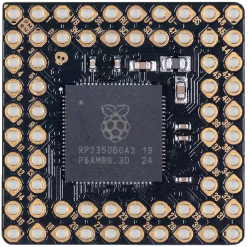
The Pimorini PGA2350 features a 16-pin SSOP package. The pinout and descriptions are as follows:

Pin Number Pin Name Description
1 VDD Positive supply voltage
2 GND Ground
3 INL+ Left channel positive input
4 INL- Left channel negative input
5 INR+ Right channel positive input
6 INR- Right channel negative input
7 OUTL Left channel output
8 OUTR Right channel output
9 SCLK SPI clock input
10 SDI SPI data input
11 CS Chip select (active low)
12 MUTE Mute control (active high)
13 NC No connection
14 NC No connection
15 NC No connection
16 NC No connection

Usage Instructions

How to Use the PGA2350 in a Circuit

  1. Power Supply: Connect the VDD pin to a stable power supply within the range of 2.7V to 5.5V. Connect the GND pin to the circuit ground.
  2. Audio Inputs: Connect the audio signal sources to the INL+/- and INR+/- pins for the left and right channels, respectively.
  3. Audio Outputs: Connect the OUTL and OUTR pins to the next stage of the audio system (e.g., speakers or further amplification stages).
  4. SPI Control: Use the SCLK, SDI, and CS pins to interface with a microcontroller or other SPI master device. The SPI interface is used to program the gain settings.
  5. Mute Function: Use the MUTE pin to enable or disable the mute function. Pull the pin high to mute the output or low to enable audio output.

Important Considerations and Best Practices

  • Decoupling Capacitors: Place decoupling capacitors (e.g., 0.1 µF and 10 µF) close to the VDD pin to ensure stable operation and minimize noise.
  • Input Coupling: Use coupling capacitors on the input pins to block DC offsets from the audio source.
  • Output Loading: Ensure the output impedance matches the load impedance for optimal performance.
  • SPI Configuration: Configure the SPI interface with the correct clock polarity and phase (CPOL = 0, CPHA = 0).
  • Gain Settings: Program the desired gain level using the SPI interface. The gain can be adjusted in 0.5 dB steps from -95.5 dB to +31.5 dB.

Example Code for Arduino UNO

Below is an example of how to control the PGA2350 using an Arduino UNO via SPI:

#include <SPI.h>

// Define SPI pins for the PGA2350
const int CS_PIN = 10; // Chip select pin

void setup() {
  // Initialize SPI communication
  SPI.begin();
  pinMode(CS_PIN, OUTPUT);
  digitalWrite(CS_PIN, HIGH); // Set CS pin high (inactive)

  // Set SPI settings: 1 MHz clock, MSB first, SPI mode 0
  SPI.beginTransaction(SPISettings(1000000, MSBFIRST, SPI_MODE0));
}

void setGain(float gain) {
  // Convert gain to PGA2350 register value
  int gainValue = (int)((gain + 95.5) * 2); // Gain in 0.5 dB steps
  byte highByte = (gainValue >> 8) & 0xFF;  // High byte of gain value
  byte lowByte = gainValue & 0xFF;          // Low byte of gain value

  // Send gain value to PGA2350
  digitalWrite(CS_PIN, LOW); // Activate chip select
  SPI.transfer(highByte);    // Send high byte
  SPI.transfer(lowByte);     // Send low byte
  digitalWrite(CS_PIN, HIGH); // Deactivate chip select
}

void loop() {
  // Example: Set gain to 10 dB
  setGain(10.0);
  delay(1000); // Wait for 1 second
}

Troubleshooting and FAQs

Common Issues and Solutions

  1. No Output Signal:

    • Ensure the MUTE pin is pulled low to enable audio output.
    • Verify that the input and output connections are correct.
    • Check the power supply voltage and ensure it is within the specified range.
  2. Distorted Audio:

    • Verify that the gain setting is appropriate for the input signal level.
    • Check for proper decoupling and coupling capacitor placement.
  3. SPI Communication Failure:

    • Ensure the SPI clock, data, and chip select connections are correct.
    • Verify that the SPI settings (clock speed, polarity, and phase) match the PGA2350 requirements.
  4. Excessive Noise:

    • Use proper grounding techniques to minimize noise.
    • Ensure the input signal source is clean and free of interference.

FAQs

Q: Can the PGA2350 be used with a 3.3V microcontroller?
A: Yes, the PGA2350 operates with a supply voltage as low as 2.7V, making it compatible with 3.3V systems.

Q: What is the maximum gain setting of the PGA2350?
A: The maximum gain is +31.5 dB, adjustable in 0.5 dB steps.

Q: Is the PGA2350 suitable for stereo audio applications?
A: Yes, the PGA2350 supports independent left and right channel inputs and outputs, making it ideal for stereo audio systems.