How to Use Omron GV5-2 12VDC 2A: Examples, Pinouts, and Specs
Introduction
The Omron GV5-2 12VDC 2A is a robust power relay module designed to switch high current loads using a low current control signal. This relay is ideal for a wide range of applications, including industrial control systems, home automation, and robotics. Its ability to handle up to 2A of current at 12VDC makes it suitable for controlling lights, motors, and other devices.
Explore Projects Built with Omron GV5-2 12VDC 2A


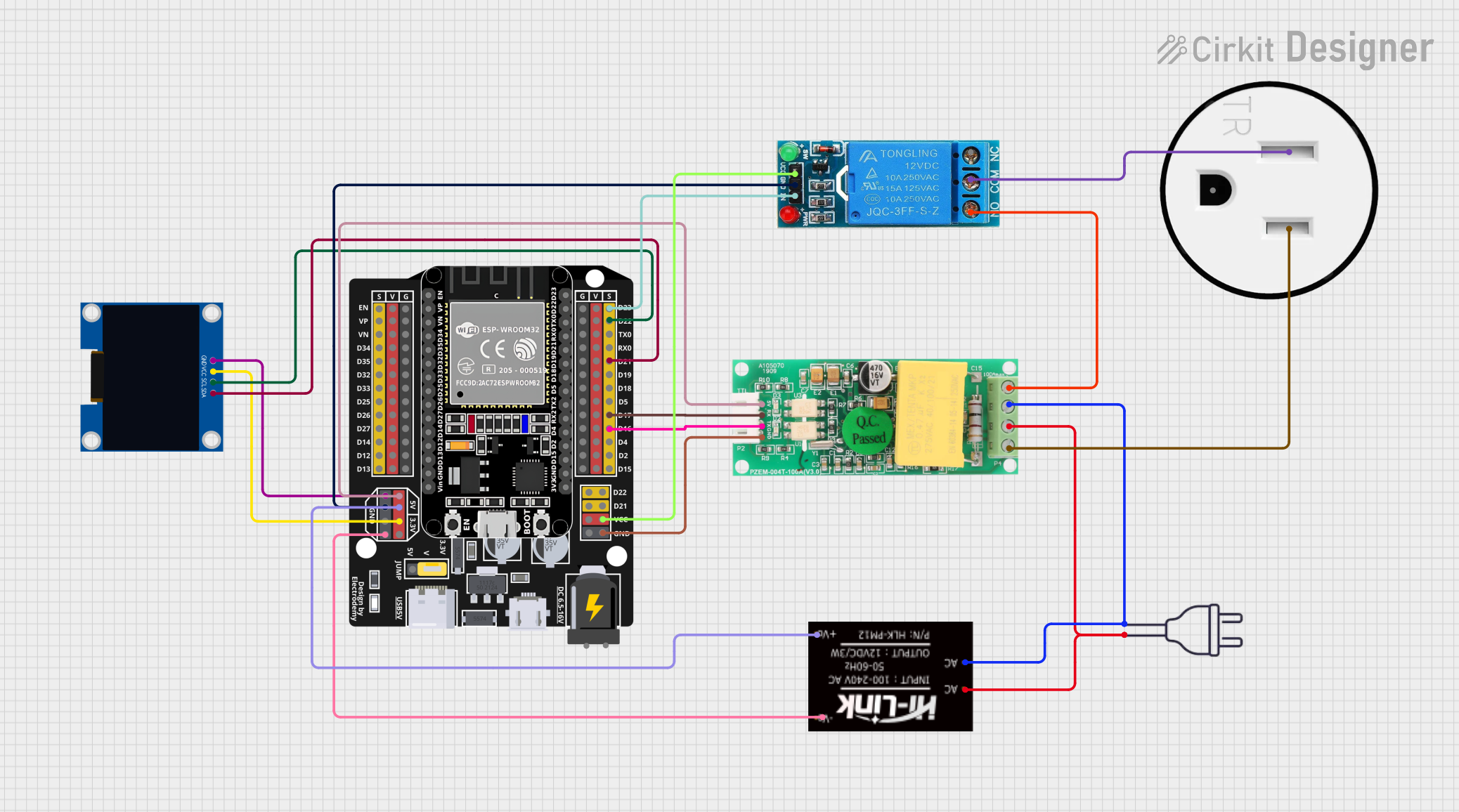
Explore Projects Built with Omron GV5-2 12VDC 2A
Technical Specifications
General Features
- Control Voltage: 12VDC
- Switching Current: Up to 2A
- Contact Type: SPDT (Single Pole Double Throw)
- Contact Material: Silver alloy
- Operate Time: Max. 10ms
- Release Time: Max. 5ms
- Mechanical Life: 10 million operations
- Electrical Life: 100,000 operations at rated load
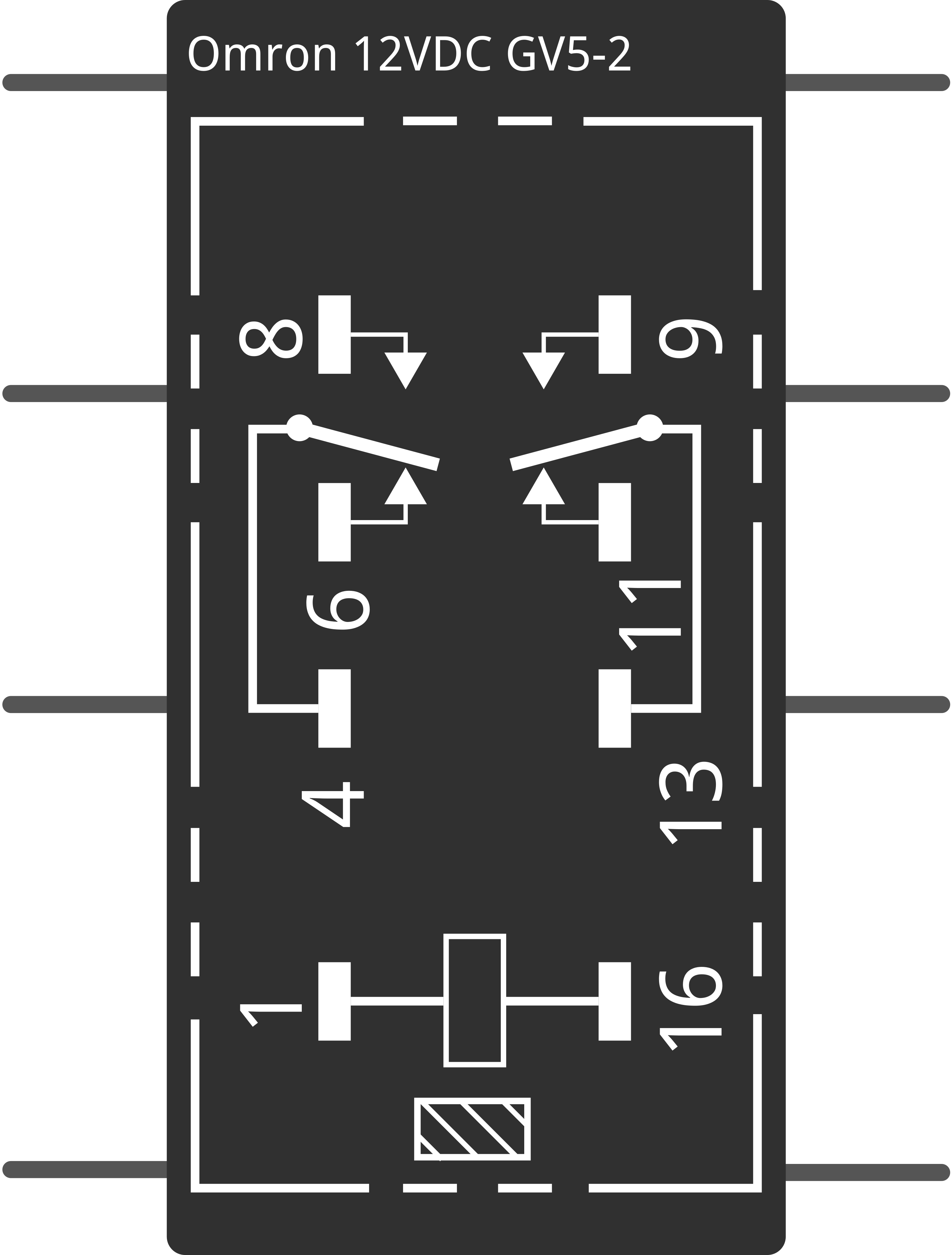
Pin Configuration and Descriptions
| Pin Number | Description | Notes |
|---|---|---|
| 1 | Coil Voltage (VCC) | Connect to 12VDC control signal |
| 2 | Coil Ground (GND) | Connect to control signal ground |
| 3 | Common (COM) | Connect to the common line of the load |
| 4 | Normally Open (NO) | Connect to the load; closed when relay is activated |
| 5 | Normally Closed (NC) | Connect to the load; closed when relay is deactivated |
Usage Instructions
Connecting the Relay to a Circuit
Powering the Coil:
- Connect pin 1 to a 12VDC power supply.
- Connect pin 2 to the ground of the control circuit.
Load Connection:
- Connect the common terminal of your load to pin 3 (COM).
- Depending on whether you want the load to be powered when the relay is activated or not, connect it to pin 4 (NO) or pin 5 (NC).
Control Signal:
- Apply a 12VDC signal to pin 1 to activate the relay.
- Remove the signal to deactivate the relay.
Best Practices
- Ensure that the load does not exceed the rated 2A current.
- Use a flyback diode across the relay coil to prevent voltage spikes when the coil is de-energized.
- Consider using a snubber circuit if the load is inductive to protect the relay contacts from arcing.
Example Code for Arduino UNO
// Define relay control pin
const int relayPin = 2;

void setup() {
  // Set the relay control pin as an output
  pinMode(relayPin, OUTPUT);
}

void loop() {
  // Turn on the relay
  digitalWrite(relayPin, HIGH);
  delay(1000); // Wait for 1 second

  // Turn off the relay
  digitalWrite(relayPin, LOW);
  delay(1000); // Wait for 1 second
}
Troubleshooting and FAQs
Common Issues
- Relay does not activate: Check the control voltage and wiring. Ensure that the control signal is 12VDC.
- Load does not power on: Verify the load current does not exceed 2A. Check the connections to NO or NC terminals.
- Intermittent operation: Inspect for loose connections or a faulty relay coil.
FAQs
Q: Can I use this relay with an AC load? A: No, the Omron GV5-2 is rated for DC loads only.
Q: What is the purpose of the NC terminal? A: The NC terminal allows the load to be connected and powered when the relay is not activated.
Q: How can I extend the life of the relay? A: Avoid switching loads that exceed the rated current and voltage. Use protective circuits like flyback diodes and snubbers.
For further assistance, consult the manufacturer's datasheet or contact technical support.