
How to Use SO08-EIAJ: Examples, Pinouts, and Specs
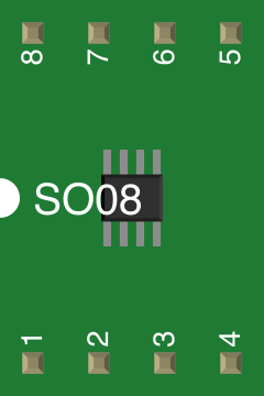
 Design with SO08-EIAJ in Cirkit Designer
Introduction
The SO08-EIAJ is a small outline integrated circuit (SOIC) package with 8 pins, designed for surface mounting on printed circuit boards (PCBs). Manufactured by Generic, this package is widely used in modern electronics due to its compact size and ease of integration. It is ideal for applications requiring efficient use of PCB space while maintaining reliable electrical connections.
Explore Projects Built with SO08-EIAJ
 Open Project in Cirkit Designer
 Open Project in Cirkit Designer
 Open Project in Cirkit Designer
 Open Project in Cirkit Designer
Explore Projects Built with SO08-EIAJ
Open Project in Cirkit DesignerOpen Project in Cirkit DesignerOpen Project in Cirkit DesignerOpen Project in Cirkit DesignerCommon Applications and Use Cases
- Microcontrollers and digital ICs
- Analog signal processing circuits
- Power management ICs
- Memory modules (e.g., EEPROM, Flash)
- Communication modules (e.g., transceivers, drivers)
- General-purpose integrated circuits in consumer electronics
Technical Specifications
The SO08-EIAJ package is designed to meet the EIAJ (Electronic Industries Association of Japan) standards, ensuring compatibility and reliability in various applications. Below are the key technical details:
Key Technical Details
- Package Type: SOIC (Small Outline Integrated Circuit)
- Number of Pins: 8
- Pin Pitch: 1.27 mm (distance between adjacent pins)
- Body Width: 3.9 mm
- Body Length: 4.9 mm
- Height: 1.75 mm (maximum)
- Lead Finish: Tin-plated (Pb-free, RoHS compliant)
- Thermal Resistance: Varies based on IC design; consult the IC datasheet
- Mounting Type: Surface Mount Technology (SMT)
Pin Configuration and Descriptions
The SO08-EIAJ package has 8 pins, typically configured as follows. Note that the specific pin functions depend on the IC housed within the package. Below is a generic pinout description:
| Pin Number | Pin Name | Description |
|---|---|---|
| 1 | VCC | Power supply input |
| 2 | IN1 | Input signal 1 |
| 3 | IN2 | Input signal 2 |
| 4 | GND | Ground connection |
| 5 | OUT1 | Output signal 1 |
| 6 | OUT2 | Output signal 2 |
| 7 | ENABLE | Enable/disable control signal |
| 8 | NC/Other | No connection or other function (varies) |
Note: The actual pin configuration depends on the specific IC housed in the SO08-EIAJ package. Always refer to the IC datasheet for precise pin functions.
Usage Instructions
How to Use the Component in a Circuit
- PCB Design: Ensure the PCB layout matches the SO08-EIAJ footprint. The pin pitch is 1.27 mm, and the pad dimensions should align with the package leads.
- Soldering: Use surface mount soldering techniques, such as reflow soldering, to attach the component to the PCB. Ensure proper alignment to avoid solder bridges.
- Power Supply: Verify the voltage and current requirements of the IC housed in the SO08-EIAJ package. Connect the VCC and GND pins appropriately.
- Signal Connections: Connect input and output signals to the respective pins as per the IC's datasheet.
- Thermal Management: If the IC generates significant heat, consider adding thermal vias or a heatsink to the PCB design.
Important Considerations and Best Practices
- ESD Protection: Handle the component with care to avoid electrostatic discharge (ESD) damage. Use an ESD-safe workstation.
- Soldering Temperature: Follow the recommended soldering temperature profile to prevent damage to the component.
- Pinout Verification: Always verify the pinout and electrical characteristics of the specific IC housed in the SO08-EIAJ package before use.
- Testing: After soldering, test the circuit to ensure proper functionality and check for soldering defects.
Example: Connecting to an Arduino UNO
If the SO08-EIAJ package houses a digital IC (e.g., a shift register), it can be interfaced with an Arduino UNO. Below is an example code snippet for interfacing a generic IC:
// Example: Interfacing a shift register in SO08-EIAJ package with Arduino UNO
// Pin connections:
// Arduino Pin 8 -> ENABLE (Pin 7 on SO08-EIAJ)
// Arduino Pin 9 -> IN1 (Pin 2 on SO08-EIAJ)
// Arduino Pin 10 -> IN2 (Pin 3 on SO08-EIAJ)
// Arduino GND -> GND (Pin 4 on SO08-EIAJ)
// Arduino 5V -> VCC (Pin 1 on SO08-EIAJ)

#define ENABLE_PIN 8
#define IN1_PIN 9
#define IN2_PIN 10

void setup() {
  pinMode(ENABLE_PIN, OUTPUT); // Set ENABLE pin as output
  pinMode(IN1_PIN, OUTPUT);    // Set IN1 pin as output
  pinMode(IN2_PIN, OUTPUT);    // Set IN2 pin as output

  digitalWrite(ENABLE_PIN, HIGH); // Enable the IC
}

void loop() {
  digitalWrite(IN1_PIN, HIGH); // Send HIGH signal to IN1
  digitalWrite(IN2_PIN, LOW);  // Send LOW signal to IN2
  delay(1000);                 // Wait for 1 second

  digitalWrite(IN1_PIN, LOW);  // Send LOW signal to IN1
  digitalWrite(IN2_PIN, HIGH); // Send HIGH signal to IN2
  delay(1000);                 // Wait for 1 second
}
Note: Modify the code and connections based on the specific IC functionality.
Troubleshooting and FAQs
Common Issues Users Might Face
Incorrect Pin Connections: Misaligned or incorrect pin connections can cause the circuit to malfunction.
- Solution: Double-check the pinout and ensure proper connections as per the IC datasheet.
Soldering Defects: Solder bridges or cold solder joints can lead to short circuits or poor connections.
- Solution: Inspect the solder joints under a magnifying glass and rework if necessary.
Overheating: Excessive heat during soldering or operation can damage the component.
- Solution: Use the recommended soldering temperature profile and ensure proper thermal management.
ESD Damage: Handling the component without proper ESD precautions can lead to failure.
- Solution: Use an ESD-safe workstation and wear an anti-static wrist strap.
FAQs
Q1: Can the SO08-EIAJ package be used for through-hole mounting?
A1: No, the SO08-EIAJ is specifically designed for surface mounting and is not suitable for through-hole applications.
Q2: How do I identify Pin 1 on the SO08-EIAJ package?
A2: Pin 1 is typically marked with a dot or notch on the package. Refer to the IC datasheet for precise identification.
Q3: What is the maximum current rating for the SO08-EIAJ package?
A3: The current rating depends on the IC housed within the package. Consult the IC datasheet for detailed specifications.
Q4: Is the SO08-EIAJ package RoHS compliant?
A4: Yes, the SO08-EIAJ package is typically RoHS compliant with lead-free tin plating. Confirm with the manufacturer for specific details.
By following this documentation, users can effectively integrate the SO08-EIAJ package into their electronic designs.