How to Use SW 420: Examples, Pinouts, and Specs
Introduction
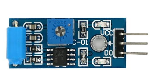
The SW 420 is a tilt switch designed to detect changes in orientation or position. It activates when tilted beyond a certain angle, making it ideal for applications requiring motion or tilt detection. This component is widely used in alarm systems, anti-theft devices, robotics, and other projects where detecting movement or inclination is essential.
Explore Projects Built with SW 420
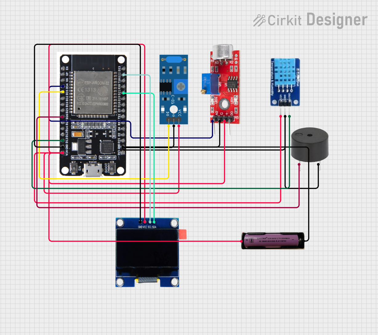
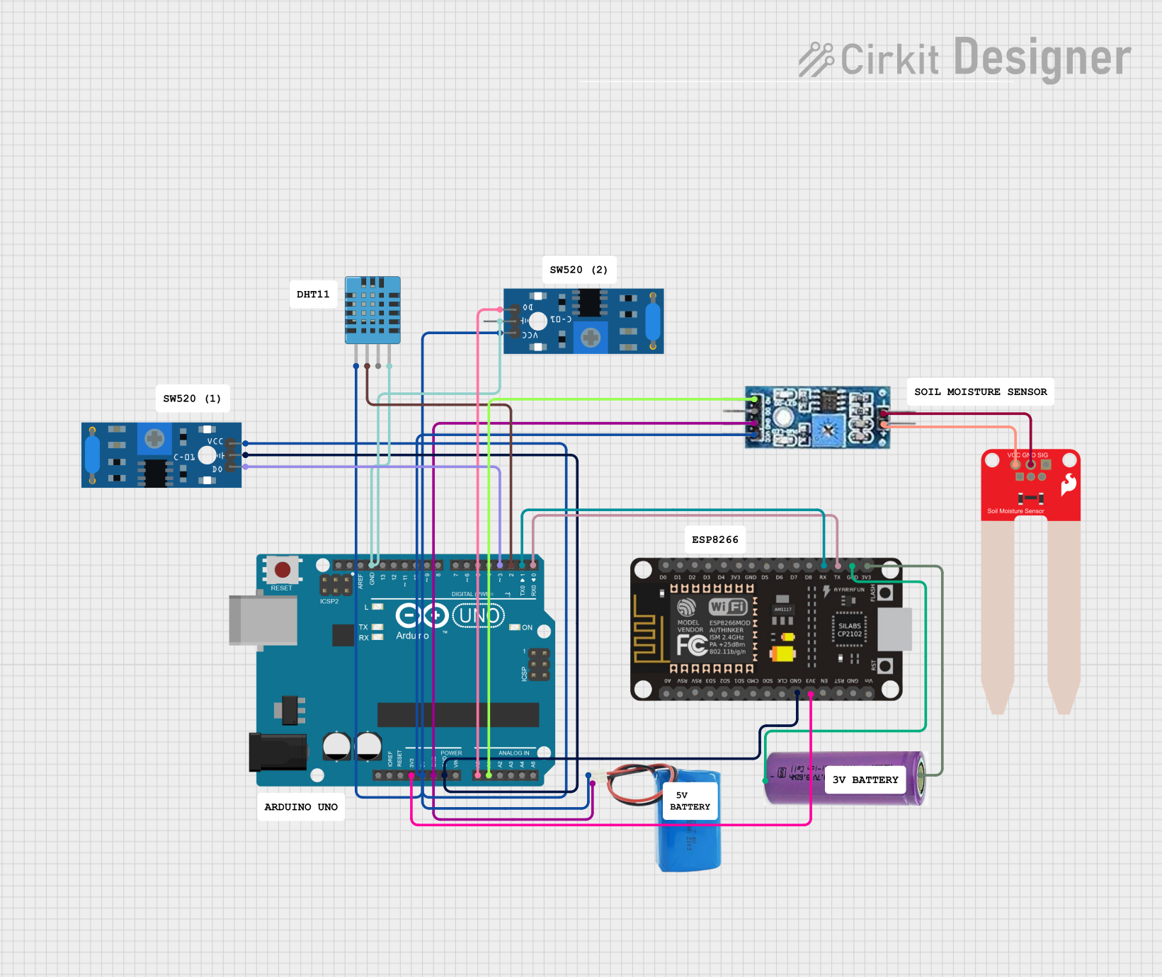
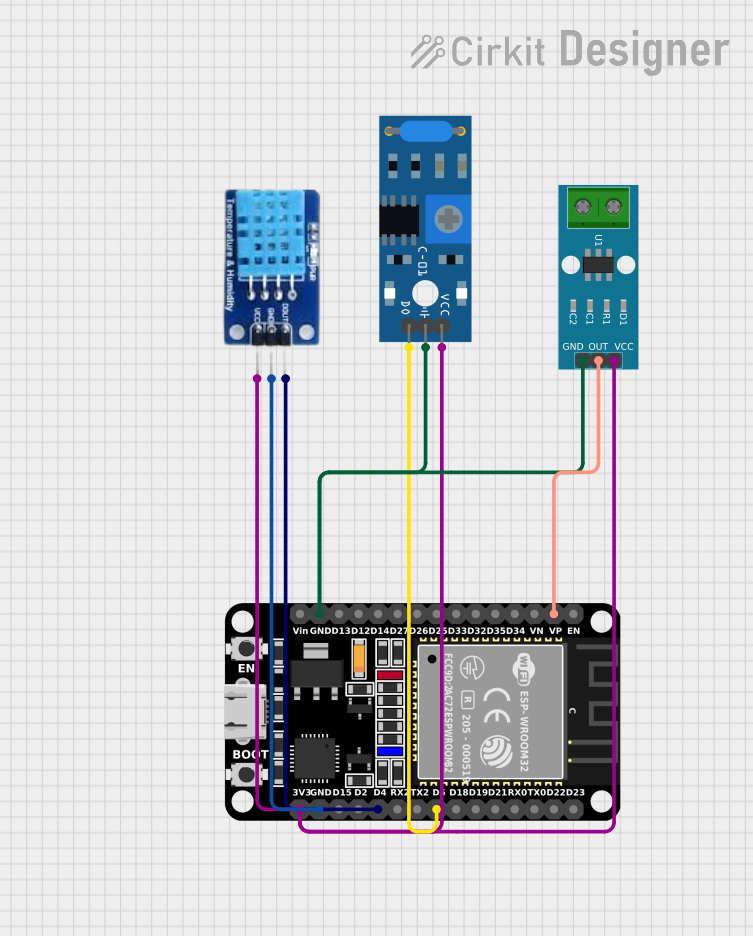
Explore Projects Built with SW 420
Technical Specifications
The SW 420 tilt switch is a simple and reliable component with the following key specifications:
- Operating Voltage: 3.3V to 5V
- Output Type: Digital (High or Low)
- Tilt Angle: Activates when tilted approximately 15° to 45° (varies slightly)
- Operating Temperature: -10°C to +50°C
- Dimensions: 14mm x 5mm (approximate)
Pin Configuration and Descriptions
The SW 420 module typically comes with three pins. Below is the pin configuration:
| Pin | Name | Description |
|---|---|---|
| 1 | VCC | Power supply pin. Connect to 3.3V or 5V. |
| 2 | GND | Ground pin. Connect to the ground of the circuit. |
| 3 | DO (OUT) | Digital output pin. Outputs HIGH when the switch is tilted, otherwise LOW. |
Usage Instructions
How to Use the SW 420 in a Circuit
- Power the Module: Connect the VCC pin to a 3.3V or 5V power source and the GND pin to the ground.
- Connect the Output: Attach the DO (OUT) pin to a digital input pin of your microcontroller or to another circuit that processes the signal.
- Monitor the Output: The output pin will provide a HIGH signal when the switch is tilted and a LOW signal when it is in its default upright position.
Important Considerations and Best Practices
- Debouncing: The SW 420 may produce noise or multiple signals when tilted. Use a software debounce routine or a capacitor to stabilize the output.
- Mounting Orientation: Ensure the switch is mounted in the correct orientation for your application to detect the desired tilt angle.
- Voltage Compatibility: Verify that the operating voltage of the SW 420 matches your circuit's power supply.
- Environmental Conditions: Avoid using the SW 420 in environments with excessive vibration or temperatures outside its operating range.
Example: Connecting SW 420 to an Arduino UNO
Below is an example of how to connect and use the SW 420 with an Arduino UNO:
Circuit Diagram
- VCC: Connect to the 5V pin on the Arduino.
- GND: Connect to the GND pin on the Arduino.
- DO (OUT): Connect to digital pin 2 on the Arduino.
Arduino Code
// SW 420 Tilt Switch Example with Arduino UNO
// This code reads the digital output of the SW 420 and prints the status to the Serial Monitor.

const int tiltPin = 2; // Pin connected to the DO (OUT) pin of the SW 420
int tiltState = 0;     // Variable to store the tilt state

void setup() {
  pinMode(tiltPin, INPUT); // Set the tilt pin as an input
  Serial.begin(9600);      // Initialize serial communication at 9600 baud
}

void loop() {
  tiltState = digitalRead(tiltPin); // Read the state of the tilt switch

  if (tiltState == HIGH) {
    // If the switch is tilted, print "Tilt Detected"
    Serial.println("Tilt Detected");
  } else {
    // If the switch is not tilted, print "No Tilt"
    Serial.println("No Tilt");
  }

  delay(500); // Wait for 500ms before reading again
}
Troubleshooting and FAQs
Common Issues and Solutions
No Output Signal:
- Cause: Incorrect wiring or loose connections.
- Solution: Double-check all connections, ensuring VCC, GND, and DO are properly connected.
Unstable or Noisy Output:
- Cause: Mechanical vibrations or lack of debouncing.
- Solution: Add a software debounce routine or a capacitor across the output pin and ground.
Output Always HIGH or LOW:
- Cause: Faulty module or incorrect orientation.
- Solution: Test the module with a multimeter and ensure it is mounted correctly.
FAQs
Q: Can the SW 420 detect precise angles?
A: No, the SW 420 is designed to detect general tilt or orientation changes, not precise angles.Q: Can I use the SW 420 with a 3.3V microcontroller?
A: Yes, the SW 420 operates at both 3.3V and 5V, making it compatible with most microcontrollers.Q: How do I reduce false triggers caused by vibrations?
A: Use a software debounce routine or add a small capacitor (e.g., 0.1µF) across the output pin and ground.
By following this documentation, you can effectively integrate the SW 420 tilt switch into your projects and troubleshoot common issues with ease.