How to Use MH-ET LIVE Scanner V3.0 : Examples, Pinouts, and Specs
MH-ET LIVE Scanner V3.0 Documentation
1. Introduction
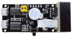
The MH-ET LIVE Scanner V3.0 is a versatile and compact device designed for scanning and analyzing electronic circuits. It provides real-time data on key electrical parameters such as voltage, current, and resistance, making it an essential tool for engineers, hobbyists, and students working on electronics projects. Its small form factor and ease of use make it ideal for both prototyping and troubleshooting.
Common Applications and Use Cases:
- Circuit Debugging: Quickly identify faults in electronic circuits.
- Prototyping: Monitor real-time electrical parameters during development.
- Educational Use: Teach and learn about circuit behavior and electrical properties.
- IoT Projects: Integrate with microcontrollers like Arduino for advanced data logging.
- Battery Testing: Measure voltage and current for battery-powered devices.
2. Technical Specifications
The following table outlines the key technical details of the MH-ET LIVE Scanner V3.0:
| Parameter | Specification |
|---|---|
| Operating Voltage | 3.3V - 5V DC |
| Measurement Range | Voltage: 0-30V, Current: 0-3A |
| Resistance Range | 0-10MΩ |
| Communication Protocol | UART (9600 baud rate) |
| Dimensions | 40mm x 20mm x 10mm |
| Weight | 5g |
Pin Configuration and Descriptions
| Pin | Name | Description |
|---|---|---|
| 1 | VCC | Power input (3.3V - 5V DC) |
| 2 | GND | Ground connection |
| 3 | TX | UART Transmit pin (sends data to external devices, e.g., Arduino) |
| 4 | RX | UART Receive pin (receives data from external devices, e.g., Arduino) |
| 5 | IN+ | Positive input for voltage/current measurement |
| 6 | IN- | Negative input for voltage/current measurement |
3. Usage Instructions
Connecting the MH-ET LIVE Scanner V3.0 to a Circuit
- Power the Scanner: Connect the VCC pin to a 3.3V or 5V power source and the GND pin to ground.
- Connect Measurement Inputs:
- For voltage measurement, connect the IN+ pin to the positive terminal of the voltage source and the IN- pin to the negative terminal.
- For current measurement, place the scanner in series with the load.
- UART Communication:
- Connect the TX pin of the scanner to the RX pin of the microcontroller (e.g., Arduino).
- Connect the RX pin of the scanner to the TX pin of the microcontroller.
Important Considerations and Best Practices
- Ensure the input voltage does not exceed 30V to avoid damaging the device.
- For current measurements, ensure the current does not exceed 3A.
- Use proper grounding to avoid noise in the measurements.
- If using with an Arduino, ensure the UART baud rate is set to 9600.
4. Example Arduino Integration
The MH-ET LIVE Scanner V3.0 can be easily integrated with an Arduino UNO for real-time data logging and analysis. Below is an example code snippet to read data from the scanner and display it on the Serial Monitor.
// Example code for interfacing MH-ET LIVE Scanner V3.0 with Arduino UNO
// This code reads voltage, current, and resistance data from the scanner
// and displays it on the Serial Monitor.

#include <SoftwareSerial.h>

// Define RX and TX pins for communication with the scanner
#define SCANNER_RX 10  // Arduino pin connected to Scanner TX
#define SCANNER_TX 11  // Arduino pin connected to Scanner RX

// Initialize SoftwareSerial for communication with the scanner
SoftwareSerial scannerSerial(SCANNER_RX, SCANNER_TX);

void setup() {
  // Start the Serial Monitor at 9600 baud rate
  Serial.begin(9600);
  // Start the scanner communication at 9600 baud rate
  scannerSerial.begin(9600);

  Serial.println("MH-ET LIVE Scanner V3.0 Initialized");
  Serial.println("Reading data...");
}

void loop() {
  // Check if data is available from the scanner
  if (scannerSerial.available()) {
    // Read and display the data from the scanner
    String scannerData = scannerSerial.readStringUntil('\n');
    Serial.println("Scanner Data: " + scannerData);
  }

  // Add a small delay to avoid flooding the Serial Monitor
  delay(100);
}
Notes:
- Connect the TX pin of the scanner to pin 10 on the Arduino and the RX pin of the scanner to pin 11.
- Open the Serial Monitor in the Arduino IDE to view the real-time data from the scanner.
5. Troubleshooting and FAQs
Common Issues and Solutions
| Issue | Possible Cause | Solution |
|---|---|---|
| No data displayed on Serial Monitor | Incorrect UART connection or baud rate | Verify TX/RX connections and ensure baud rate is set to 9600. |
| Incorrect voltage/current readings | Exceeding measurement range or noise | Ensure input is within specified range and check for proper grounding. |
| Device not powering on | Insufficient power supply | Ensure the VCC pin is connected to a 3.3V or 5V power source. |
| Data appears garbled on Serial Monitor | Mismatched baud rate | Ensure both Arduino and scanner are set to the same baud rate (9600). |
Frequently Asked Questions (FAQs)
Can the scanner measure AC voltage or current?
- No, the MH-ET LIVE Scanner V3.0 is designed for DC voltage and current measurements only.
What happens if I exceed the voltage or current range?
- Exceeding the specified range may damage the device. Always ensure inputs are within the safe operating limits.
Can I use the scanner with a 3.3V microcontroller?
- Yes, the scanner is compatible with both 3.3V and 5V systems.
How do I calibrate the scanner?
- The scanner is pre-calibrated from the factory. If calibration is required, refer to the manufacturer's advanced documentation.
6. Conclusion
The MH-ET LIVE Scanner V3.0 is a powerful and compact tool for real-time circuit analysis. Its ease of integration with microcontrollers like Arduino makes it a valuable addition to any electronics toolkit. By following the guidelines and best practices outlined in this documentation, users can maximize the performance and lifespan of the device. For further assistance, consult the manufacturer's support resources.
Explore Projects Built with MH-ET LIVE Scanner V3.0

Explore Projects Built with MH-ET LIVE Scanner V3.0