How to Use 7 Channel IR Sensor: Examples, Pinouts, and Specs
Introduction
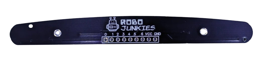
The 7 Channel IR Sensor by Robojunkies (Part ID: IR sensor) is a versatile infrared sensor module designed to detect infrared light across seven independent channels. This allows the sensor to detect multiple objects or obstacles simultaneously, making it ideal for applications in robotics, automation, and line-following robots. Its ability to sense infrared light with precision makes it a popular choice for navigation, obstacle avoidance, and object detection tasks.
Explore Projects Built with 7 Channel IR Sensor
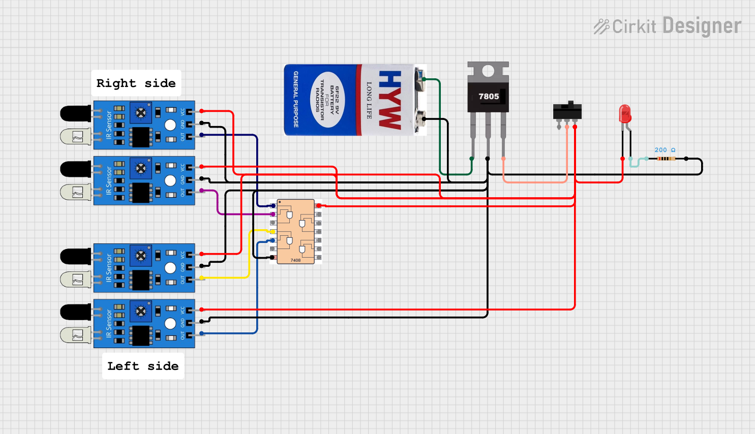

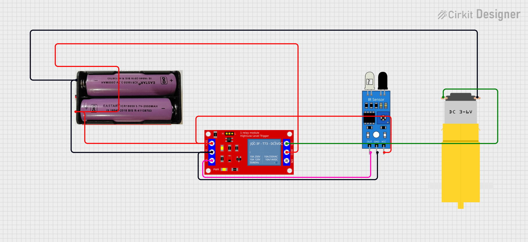
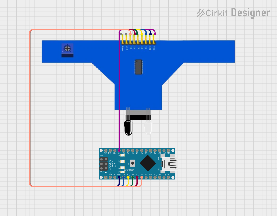
Explore Projects Built with 7 Channel IR Sensor
Common Applications
- Line-following robots
- Obstacle detection and avoidance
- Edge detection for robotic platforms
- Industrial automation systems
- Multi-object tracking in robotics
Technical Specifications
The following table outlines the key technical details of the 7 Channel IR Sensor:
| Parameter | Specification |
|---|---|
| Operating Voltage | 3.3V - 5V DC |
| Operating Current | ≤ 100mA |
| Detection Range | 2cm - 30cm (adjustable via potentiometer) |
| Output Type | Digital (High/Low) |
| Number of Channels | 7 |
| IR Wavelength | 940nm |
| Dimensions | 100mm x 15mm x 10mm |
| Weight | 15g |
Pin Configuration
The 7 Channel IR Sensor has the following pin configuration:
| Pin Name | Description |
|---|---|
| VCC | Power supply input (3.3V - 5V DC) |
| GND | Ground |
| OUT1 - OUT7 | Digital outputs for each of the 7 IR channels |
| EN | Enable pin (active HIGH to enable the sensor) |
Usage Instructions
Connecting the Sensor
- Power Supply: Connect the
VCCpin to a 3.3V or 5V power source and theGNDpin to ground. - Digital Outputs: Connect the
OUT1toOUT7pins to the digital input pins of your microcontroller or microprocessor. Each output corresponds to one of the seven IR channels. - Enable Pin: Ensure the
ENpin is set HIGH to activate the sensor. If left LOW, the sensor will remain disabled.
Adjusting the Detection Range
- Use the onboard potentiometer to adjust the detection range of the sensor. Turning the potentiometer clockwise increases the range, while turning it counterclockwise decreases the range.
Example: Using with Arduino UNO
Below is an example of how to use the 7 Channel IR Sensor with an Arduino UNO to detect obstacles:
// Define the digital pins connected to the sensor outputs
#define SENSOR1 2  // OUT1 connected to pin 2
#define SENSOR2 3  // OUT2 connected to pin 3
#define SENSOR3 4  // OUT3 connected to pin 4
#define SENSOR4 5  // OUT4 connected to pin 5
#define SENSOR5 6  // OUT5 connected to pin 6
#define SENSOR6 7  // OUT6 connected to pin 7
#define SENSOR7 8  // OUT7 connected to pin 8

void setup() {
  // Initialize serial communication for debugging
  Serial.begin(9600);

  // Set sensor pins as inputs
  pinMode(SENSOR1, INPUT);
  pinMode(SENSOR2, INPUT);
  pinMode(SENSOR3, INPUT);
  pinMode(SENSOR4, INPUT);
  pinMode(SENSOR5, INPUT);
  pinMode(SENSOR6, INPUT);
  pinMode(SENSOR7, INPUT);
}

void loop() {
  // Read the state of each sensor
  int sensor1State = digitalRead(SENSOR1);
  int sensor2State = digitalRead(SENSOR2);
  int sensor3State = digitalRead(SENSOR3);
  int sensor4State = digitalRead(SENSOR4);
  int sensor5State = digitalRead(SENSOR5);
  int sensor6State = digitalRead(SENSOR6);
  int sensor7State = digitalRead(SENSOR7);

  // Print the sensor states to the Serial Monitor
  Serial.print("S1: "); Serial.print(sensor1State);
  Serial.print(" S2: "); Serial.print(sensor2State);
  Serial.print(" S3: "); Serial.print(sensor3State);
  Serial.print(" S4: "); Serial.print(sensor4State);
  Serial.print(" S5: "); Serial.print(sensor5State);
  Serial.print(" S6: "); Serial.print(sensor6State);
  Serial.print(" S7: "); Serial.println(sensor7State);

  // Add a small delay to avoid flooding the Serial Monitor
  delay(100);
}
Best Practices
- Ensure the sensor is mounted at an appropriate height for optimal detection.
- Avoid exposing the sensor to direct sunlight or strong ambient IR sources, as this may interfere with its performance.
- Use decoupling capacitors near the power pins to reduce noise and improve stability.
Troubleshooting and FAQs
Common Issues
No Output Detected:
- Ensure the
ENpin is set HIGH to enable the sensor. - Verify the power supply voltage is within the specified range (3.3V - 5V).
- Check the connections to the microcontroller or other devices.
- Ensure the
Inconsistent Readings:
- Adjust the potentiometer to fine-tune the detection range.
- Ensure there are no reflective surfaces or strong IR sources nearby.
All Outputs are HIGH or LOW:
- Verify that the sensor is not obstructed or exposed to excessive ambient IR light.
- Check for loose or incorrect wiring.
FAQs
Q: Can the sensor detect objects beyond 30cm?
A: The detection range is limited to 30cm. For longer ranges, consider using other IR sensors designed for extended distances.
Q: Can I use this sensor with a 3.3V microcontroller?
A: Yes, the sensor is compatible with both 3.3V and 5V systems.
Q: How do I know which channel detects an object?
A: Each channel has a dedicated digital output pin (OUT1 to OUT7). When an object is detected, the corresponding output pin goes LOW.
Q: Can I use fewer than 7 channels?
A: Yes, you can use only the channels you need by connecting the corresponding output pins to your microcontroller.
By following this documentation, you can effectively integrate the 7 Channel IR Sensor into your projects and troubleshoot any issues that arise.