Cirkit Designer Logo
Cirkit Designer
Your all-in-one circuit design IDE
Home / 
Component Documentation

How to Use Type-c Power Bank Module: Examples, Pinouts, and Specs

Image of Type-c Power Bank Module
Cirkit Designer LogoDesign with Type-c Power Bank Module in Cirkit Designer

Introduction

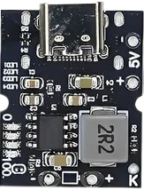
The Type-C Power Bank Module is a compact and versatile electronic component designed for energy storage and delivery. Manufactured by Arduino/ESP32, this module features a USB Type-C interface for efficient charging and discharging of devices. It is commonly used in portable power bank applications, DIY electronics projects, and as a power supply for microcontroller-based systems.

Explore Projects Built with Type-c Power Bank Module

Use Cirkit Designer to design, explore, and prototype these projects online. Some projects support real-time simulation. Click "Open Project" to start designing instantly!
Battery-Powered Lora G2 Node Station with 18650 Li-ion Batteries and Boost Converter
Image of Custom-Lora-G2-Node: A project utilizing Type-c Power Bank Module in a practical application
This circuit is a portable power supply system that uses multiple 18650 Li-ion batteries to provide a stable 5V output through a boost converter. It includes a fast charging module with a USB-C input for recharging the batteries and a battery indicator for monitoring the battery status. The system powers a Lora G2 Node Station, making it suitable for wireless communication applications.
Cirkit Designer LogoOpen Project in Cirkit Designer
Battery-Powered 18650 Li-ion Charger with USB Output and Adjustable Voltage Regulator
Image of Breadboard: A project utilizing Type-c Power Bank Module in a practical application
This circuit is a battery management and power supply system that uses three 3.7V batteries connected to a 3S 10A Li-ion 18650 Charger Protection Board Module for balanced charging and protection. The system includes a TP4056 Battery Charging Protection Module for additional charging safety, a Step Up Boost Power Converter to regulate and boost the voltage, and a USB regulator to provide a stable 5V output, controlled by a push switch.
Cirkit Designer LogoOpen Project in Cirkit Designer
Battery-Powered Boost Converter with USB Type-C and BMS
Image of Weird Case: A project utilizing Type-c Power Bank Module in a practical application
This circuit is a power management and conversion system that includes a boost converter, battery management system (BMS), and various MOSFETs and passive components. It is designed to regulate and boost the voltage from a 2000mAh battery, providing stable power output through a USB Type C interface. The circuit also includes protection and switching mechanisms to ensure safe and efficient power delivery.
Cirkit Designer LogoOpen Project in Cirkit Designer
Battery-Powered UPS System with Waveshare UPS 3S and Solar Charger
Image of Copy of s: A project utilizing Type-c Power Bank Module in a practical application
This circuit is a power management system that integrates a 12V power supply, a solar charger power bank, and multiple Li-ion batteries to provide a stable power output. The Waveshare UPS 3S manages the input from the power sources and batteries, ensuring continuous power delivery. The MRB045 module is used to interface the solar charger with the rest of the system.
Cirkit Designer LogoOpen Project in Cirkit Designer

Explore Projects Built with Type-c Power Bank Module

Use Cirkit Designer to design, explore, and prototype these projects online. Some projects support real-time simulation. Click "Open Project" to start designing instantly!
Image of Custom-Lora-G2-Node: A project utilizing Type-c Power Bank Module in a practical application
Battery-Powered Lora G2 Node Station with 18650 Li-ion Batteries and Boost Converter
This circuit is a portable power supply system that uses multiple 18650 Li-ion batteries to provide a stable 5V output through a boost converter. It includes a fast charging module with a USB-C input for recharging the batteries and a battery indicator for monitoring the battery status. The system powers a Lora G2 Node Station, making it suitable for wireless communication applications.
Cirkit Designer LogoOpen Project in Cirkit Designer
Image of Breadboard: A project utilizing Type-c Power Bank Module in a practical application
Battery-Powered 18650 Li-ion Charger with USB Output and Adjustable Voltage Regulator
This circuit is a battery management and power supply system that uses three 3.7V batteries connected to a 3S 10A Li-ion 18650 Charger Protection Board Module for balanced charging and protection. The system includes a TP4056 Battery Charging Protection Module for additional charging safety, a Step Up Boost Power Converter to regulate and boost the voltage, and a USB regulator to provide a stable 5V output, controlled by a push switch.
Cirkit Designer LogoOpen Project in Cirkit Designer
Image of Weird Case: A project utilizing Type-c Power Bank Module in a practical application
Battery-Powered Boost Converter with USB Type-C and BMS
This circuit is a power management and conversion system that includes a boost converter, battery management system (BMS), and various MOSFETs and passive components. It is designed to regulate and boost the voltage from a 2000mAh battery, providing stable power output through a USB Type C interface. The circuit also includes protection and switching mechanisms to ensure safe and efficient power delivery.
Cirkit Designer LogoOpen Project in Cirkit Designer
Image of Copy of s: A project utilizing Type-c Power Bank Module in a practical application
Battery-Powered UPS System with Waveshare UPS 3S and Solar Charger
This circuit is a power management system that integrates a 12V power supply, a solar charger power bank, and multiple Li-ion batteries to provide a stable power output. The Waveshare UPS 3S manages the input from the power sources and batteries, ensuring continuous power delivery. The MRB045 module is used to interface the solar charger with the rest of the system.
Cirkit Designer LogoOpen Project in Cirkit Designer

Common Applications and Use Cases

  • Portable power banks for charging smartphones, tablets, and other USB devices.
  • Power supply for Arduino, ESP32, and other microcontroller projects.
  • Backup power solutions for small electronic devices.
  • DIY electronics projects requiring a rechargeable power source.

Technical Specifications

The following table outlines the key technical details of the Type-C Power Bank Module:

Parameter Specification
Input Voltage 5V (via USB Type-C port)
Output Voltage 5V (regulated)
Output Current Up to 2A
Battery Compatibility 3.7V Li-ion/LiPo battery
Charging Current 1A (default, adjustable in some models)
Protection Features Overcharge, over-discharge, short circuit
Dimensions 25mm x 20mm x 5mm

Pin Configuration and Descriptions

The module typically includes the following pins and interfaces:

Pin/Interface Description
USB Type-C Port Used for charging the connected battery and powering external devices.
BAT+ Positive terminal for connecting the 3.7V Li-ion/LiPo battery.
BAT- Negative terminal for connecting the 3.7V Li-ion/LiPo battery.
OUT+ Positive output terminal for powering external devices.
OUT- Negative output terminal for powering external devices.
Indicator LEDs Status LEDs for charging, discharging, and battery level indication.

Usage Instructions

How to Use the Component in a Circuit

  1. Connect the Battery: Attach a 3.7V Li-ion or LiPo battery to the BAT+ and BAT- terminals. Ensure correct polarity to avoid damage.
  2. Power Input: Use a USB Type-C cable to connect the module to a 5V power source for charging the battery.
  3. Power Output: Connect your load (e.g., Arduino, ESP32, or other devices) to the OUT+ and OUT- terminals. The module will regulate the output to 5V.
  4. Monitor Status: Use the onboard indicator LEDs to monitor charging, discharging, and battery status.

Important Considerations and Best Practices

  • Battery Selection: Use only compatible 3.7V Li-ion or LiPo batteries with appropriate capacity and discharge ratings.
  • Heat Management: Avoid overloading the module to prevent overheating. Ensure proper ventilation if used in enclosed spaces.
  • Polarity Check: Double-check all connections to ensure correct polarity, especially for the battery terminals.
  • Arduino/ESP32 Integration: When powering an Arduino or ESP32, connect the OUT+ to the 5V pin and OUT- to GND.

Example Code for Arduino UNO

If you are using the Type-C Power Bank Module to power an Arduino UNO, you can monitor the battery voltage using an analog pin. Here's an example:

// Example code to monitor battery voltage using Arduino UNO
const int batteryPin = A0; // Analog pin connected to battery voltage divider
float batteryVoltage = 0.0;

void setup() {
  Serial.begin(9600); // Initialize serial communication
  pinMode(batteryPin, INPUT); // Set the battery pin as input
}

void loop() {
  int sensorValue = analogRead(batteryPin); // Read the analog value
  // Convert the analog value to voltage (assuming a 10-bit ADC and 5V reference)
  batteryVoltage = (sensorValue / 1023.0) * 5.0;
  
  // Print the battery voltage to the Serial Monitor
  Serial.print("Battery Voltage: ");
  Serial.print(batteryVoltage);
  Serial.println(" V");
  
  delay(1000); // Wait for 1 second before the next reading
}

Note: Use a voltage divider circuit if the battery voltage exceeds the Arduino's ADC input range.

Troubleshooting and FAQs

Common Issues and Solutions

  1. Module Not Charging the Battery:

    • Ensure the USB Type-C cable and power source are functioning properly.
    • Verify the battery is connected with the correct polarity.
    • Check for any physical damage to the module.
  2. No Output Voltage:

    • Confirm the battery is charged and connected correctly.
    • Inspect the OUT+ and OUT- connections for loose wires or poor contact.
  3. Overheating:

    • Reduce the load current if the module becomes excessively hot.
    • Ensure proper ventilation around the module.
  4. LED Indicators Not Working:

    • Verify the module is receiving power.
    • Check for damaged or faulty LEDs.

FAQs

Q1: Can I use this module with a 12V battery?
A1: No, this module is designed for 3.7V Li-ion or LiPo batteries only. Using a 12V battery may damage the module.

Q2: What is the maximum load current the module can handle?
A2: The module can handle up to 2A of output current. Exceeding this limit may trigger the protection circuit or damage the module.

Q3: Can I charge the battery and power a device simultaneously?
A3: Yes, the module supports simultaneous charging and discharging, but ensure the total current does not exceed the module's capacity.

Q4: How do I adjust the charging current?
A4: Some models allow adjustment of the charging current via onboard resistors or jumpers. Refer to the specific model's datasheet for details.