
How to Use Red Pushbutton: Examples, Pinouts, and Specs
 Design with Red Pushbutton in Cirkit Designer
Introduction
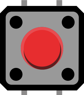
The Red Pushbutton is a momentary switch that is activated when pressed. It is commonly used to control circuits or devices by temporarily completing or breaking a connection. This versatile component is widely utilized in applications such as user input interfaces, reset buttons, and control panels. Its simple design and ease of use make it a staple in both beginner and advanced electronic projects.
Explore Projects Built with Red Pushbutton
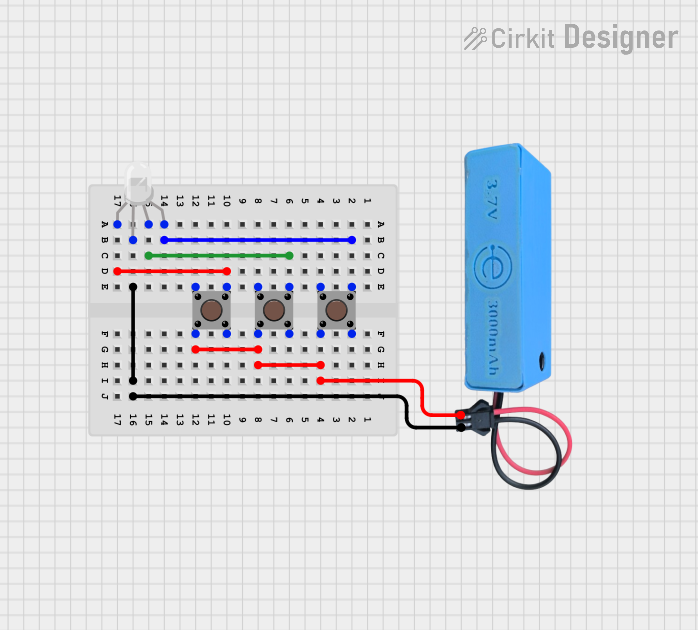 Open Project in Cirkit Designer
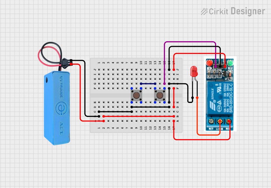 Open Project in Cirkit Designer
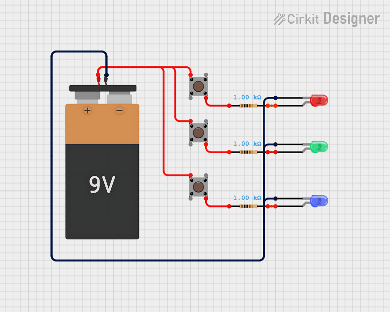 Open Project in Cirkit Designer
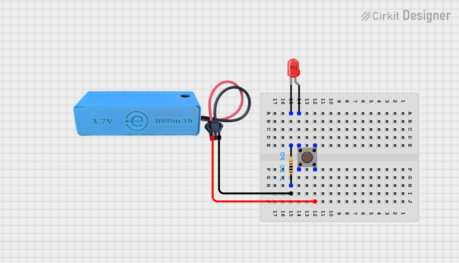 Open Project in Cirkit Designer
Explore Projects Built with Red Pushbutton
Open Project in Cirkit DesignerOpen Project in Cirkit DesignerOpen Project in Cirkit DesignerOpen Project in Cirkit DesignerTechnical Specifications
- Type: Momentary pushbutton switch
- Color: Red
- Contact Configuration: Normally Open (NO)
- Rated Voltage: 12V DC (typical)
- Rated Current: 50mA to 1A (depending on model)
- Contact Resistance: ≤ 50 mΩ
- Insulation Resistance: ≥ 100 MΩ
- Operating Temperature: -20°C to +70°C
- Mechanical Durability: 100,000 cycles (typical)
Pin Configuration and Descriptions
The Red Pushbutton typically has two or four pins, depending on the model. Below is a description of the pin configuration:
For 2-Pin Pushbutton:
| Pin Number | Description |
|---|---|
| 1 | Terminal 1 for circuit connection |
| 2 | Terminal 2 for circuit connection |
For 4-Pin Pushbutton:
| Pin Number | Description |
|---|---|
| 1 | Terminal 1 for circuit connection |
| 2 | Terminal 2 for circuit connection |
| 3 | Duplicate of Terminal 1 |
| 4 | Duplicate of Terminal 2 |
Note: In a 4-pin pushbutton, pins 1 and 3 are internally connected, as are pins 2 and 4.
Usage Instructions
How to Use the Red Pushbutton in a Circuit
- Identify the Pins: For a 2-pin pushbutton, connect one pin to the input signal and the other to ground. For a 4-pin pushbutton, use any pair of internally connected pins.
- Connect to Power: Ensure the pushbutton is connected to a power source within its rated voltage and current limits.
- Debounce the Signal: Pushbuttons can produce noise or "bouncing" when pressed. Use a capacitor or software debounce logic to stabilize the signal.
- Test the Circuit: Verify the pushbutton completes the circuit when pressed and breaks it when released.
Important Considerations and Best Practices
- Voltage and Current Ratings: Do not exceed the rated voltage and current to avoid damaging the pushbutton.
- Debouncing: Always implement debouncing to ensure reliable operation in digital circuits.
- Mounting: Secure the pushbutton properly to prevent mechanical stress on the pins.
- Polarity: The pushbutton is non-polarized, so it can be connected in either orientation.
Example: Connecting the Red Pushbutton to an Arduino UNO
Below is an example of how to use the Red Pushbutton with an Arduino UNO to toggle an LED:
// Define pin numbers
const int buttonPin = 2;  // Pushbutton connected to digital pin 2
const int ledPin = 13;    // LED connected to digital pin 13

// Variable to store button state
int buttonState = 0;

void setup() {
  pinMode(buttonPin, INPUT_PULLUP); // Set button pin as input with internal pull-up
  pinMode(ledPin, OUTPUT);         // Set LED pin as output
}

void loop() {
  buttonState = digitalRead(buttonPin); // Read the state of the pushbutton

  if (buttonState == LOW) { // Button pressed (LOW due to pull-up resistor)
    digitalWrite(ledPin, HIGH); // Turn on the LED
  } else {
    digitalWrite(ledPin, LOW);  // Turn off the LED
  }
}
Note: The internal pull-up resistor is enabled to simplify the circuit, eliminating the need for an external resistor.
Troubleshooting and FAQs
Common Issues
Pushbutton Not Responding:
- Cause: Loose or incorrect wiring.
- Solution: Double-check the connections and ensure the pushbutton is properly secured.
Button Press Produces Erratic Behavior:
- Cause: Signal bouncing.
- Solution: Add a 0.1µF capacitor across the pushbutton terminals or implement software debouncing.
LED Does Not Turn On in Arduino Circuit:
- Cause: Incorrect pin configuration or faulty pushbutton.
- Solution: Verify the pin numbers in the code and test the pushbutton with a multimeter.
FAQs
Q: Can I use the Red Pushbutton with AC circuits?
A: The pushbutton is primarily designed for low-voltage DC circuits. Check the datasheet for AC compatibility.Q: How do I test if the pushbutton is working?
A: Use a multimeter in continuity mode. Press the button; the multimeter should beep when the circuit is completed.Q: Can I use the pushbutton to control high-power devices?
A: No, the pushbutton is not rated for high-power applications. Use it to control a relay or transistor for such purposes.