How to Use CL42T Stepper driver: Examples, Pinouts, and Specs
Introduction
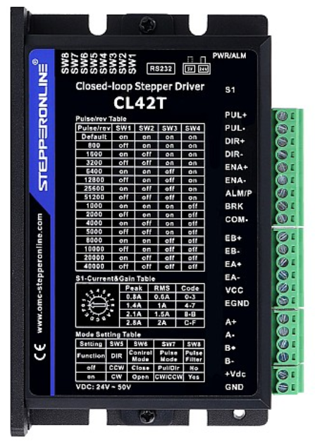
The CL42T Stepper Driver, manufactured by Stepper Online, is an advanced electronic device designed to control the motion of stepper motors. It provides precise control over speed, position, and torque, making it an essential component in various applications requiring accurate motor control.
Explore Projects Built with CL42T Stepper driver


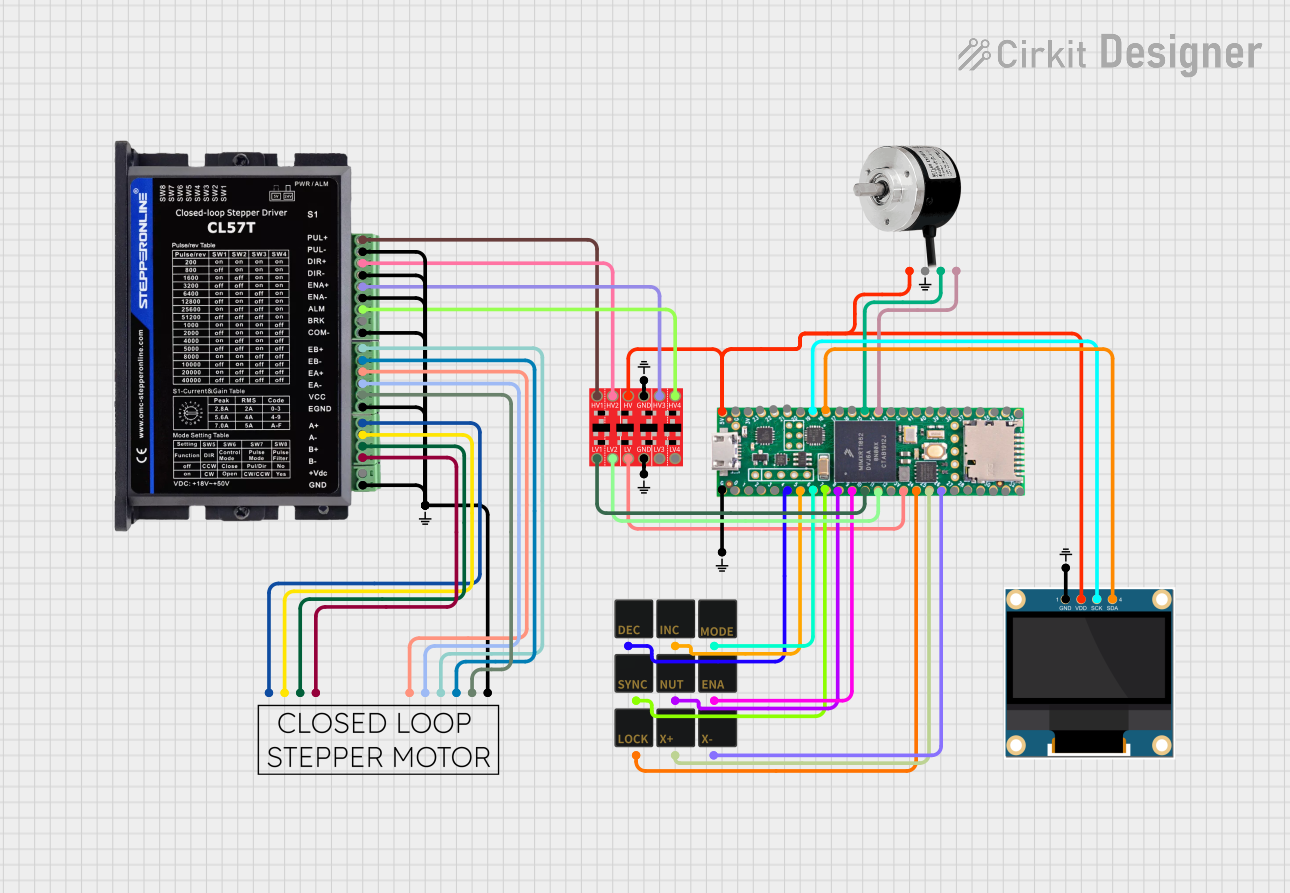
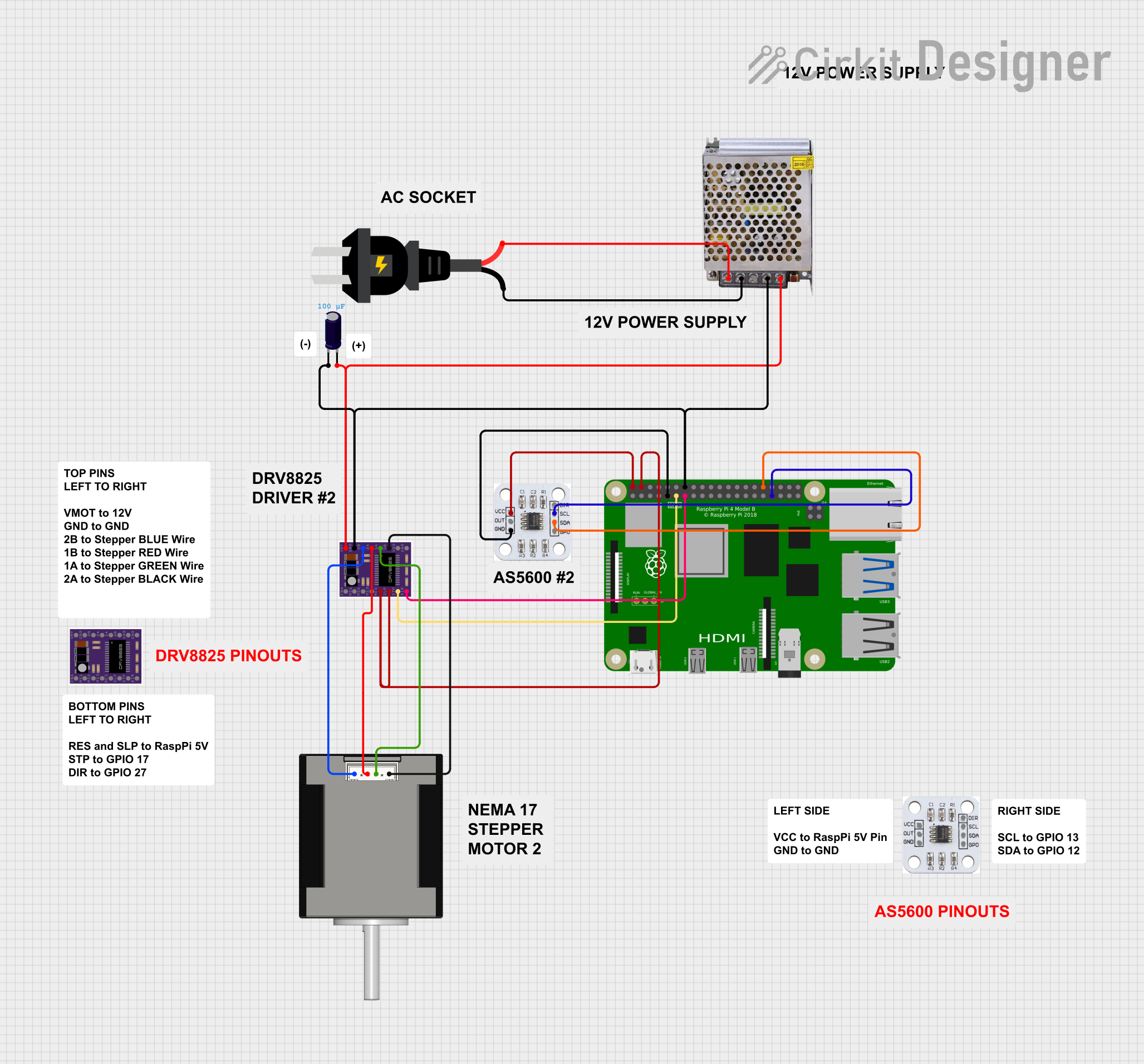
Explore Projects Built with CL42T Stepper driver
Common Applications and Use Cases
- 3D Printers: Ensures precise movement of the print head and build platform.
- CNC Machines: Provides accurate control of cutting tools for intricate designs.
- Robotics: Enables precise movement and positioning of robotic arms and components.
- Automated Conveyor Systems: Controls the speed and position of conveyor belts for efficient material handling.
- Medical Devices: Used in equipment requiring precise motor control, such as infusion pumps and imaging devices.
Technical Specifications
Key Technical Details
| Parameter | Value |
|---|---|
| Supply Voltage | 20V - 50V DC |
| Output Current | 1.0A - 4.2A |
| Microstep Settings | 1, 2, 4, 8, 16, 32 |
| Control Signal | Pulse/Direction, Enable |
| Operating Temperature | -10°C to +45°C |
| Storage Temperature | -40°C to +70°C |
| Humidity | 40% - 90% RH (non-condensing) |
Pin Configuration and Descriptions
| Pin Number | Pin Name | Description |
|---|---|---|
| 1 | PUL+ | Pulse signal input (+5V) |
| 2 | PUL- | Pulse signal input (GND) |
| 3 | DIR+ | Direction signal input (+5V) |
| 4 | DIR- | Direction signal input (GND) |
| 5 | ENA+ | Enable signal input (+5V) |
| 6 | ENA- | Enable signal input (GND) |
| 7 | A+ | Motor phase A+ |
| 8 | A- | Motor phase A- |
| 9 | B+ | Motor phase B+ |
| 10 | B- | Motor phase B- |
| 11 | VCC | Power supply input (20V - 50V DC) |
| 12 | GND | Power supply ground |
Usage Instructions
How to Use the Component in a Circuit
Power Supply Connection:
- Connect the VCC pin to a DC power supply (20V - 50V).
- Connect the GND pin to the ground of the power supply.
Motor Connection:
- Connect the stepper motor's phase A wires to the A+ and A- pins.
- Connect the stepper motor's phase B wires to the B+ and B- pins.
Control Signal Connection:
- Connect the PUL+ and PUL- pins to the pulse signal output of the controller.
- Connect the DIR+ and DIR- pins to the direction signal output of the controller.
- Optionally, connect the ENA+ and ENA- pins to the enable signal output of the controller.
Microstep Settings:
- Set the microstep settings using the DIP switches on the driver according to the desired resolution.
Important Considerations and Best Practices
- Heat Dissipation: Ensure proper ventilation or use a heat sink to prevent overheating.
- Wiring: Use appropriate gauge wires for power and motor connections to handle the current.
- Signal Integrity: Use shielded cables for control signals to minimize noise and interference.
- Power Supply: Use a stable and regulated power supply to avoid voltage fluctuations.
Troubleshooting and FAQs
Common Issues Users Might Face
Motor Not Moving:
- Solution: Check the power supply connections and ensure the voltage is within the specified range. Verify the control signal connections and ensure the pulse and direction signals are being sent correctly.
Motor Moving Erratically:
- Solution: Check the wiring of the motor phases and ensure they are connected correctly. Verify the microstep settings and adjust if necessary. Ensure the control signals are clean and free from noise.
Overheating:
- Solution: Ensure proper ventilation and consider using a heat sink. Check the current settings and reduce if necessary.
No Response to Control Signals:
- Solution: Verify the control signal connections and ensure the signals are within the specified voltage range. Check the enable signal and ensure it is active.
Solutions and Tips for Troubleshooting
- Check Connections: Ensure all connections are secure and correctly wired.
- Use a Multimeter: Measure the voltage and current at various points to diagnose issues.
- Consult the Datasheet: Refer to the manufacturer's datasheet for detailed information and specifications.
- Test with a Known Good Motor: Use a motor that is known to be working to isolate the issue.
Example Code for Arduino UNO
// Example code to control a stepper motor using the CL42T Stepper Driver
// and an Arduino UNO

const int pulsePin = 2; // Pulse signal pin
const int dirPin = 3;   // Direction signal pin
const int enaPin = 4;   // Enable signal pin

void setup() {
  pinMode(pulsePin, OUTPUT);
  pinMode(dirPin, OUTPUT);
  pinMode(enaPin, OUTPUT);

  digitalWrite(enaPin, HIGH); // Enable the driver
  digitalWrite(dirPin, HIGH); // Set direction
}

void loop() {
  digitalWrite(pulsePin, HIGH); // Generate pulse
  delayMicroseconds(500);       // Adjust delay for speed control
  digitalWrite(pulsePin, LOW);
  delayMicroseconds(500);
}
This example code demonstrates how to control a stepper motor using the CL42T Stepper Driver and an Arduino UNO. Adjust the delayMicroseconds values to control the speed of the motor.
By following this documentation, users can effectively utilize the CL42T Stepper Driver in their projects, ensuring precise and reliable motor control.