How to Use 2N7002: Examples, Pinouts, and Specs
Introduction
The 2N7002 is an N-channel MOSFET (Metal-Oxide-Semiconductor Field-Effect Transistor) designed for switching and amplifying electronic signals. It is widely used in low-power circuits due to its low on-resistance, fast switching speeds, and compact SOT-23 package. This component is ideal for applications requiring efficient signal control and low power dissipation.
Explore Projects Built with 2N7002

Explore Projects Built with 2N7002
Common Applications
- Signal switching in digital circuits
- Low-power DC-DC converters
- Load switching in battery-powered devices
- Level shifting in microcontroller circuits
- General-purpose amplification
Technical Specifications
Key Specifications
| Parameter | Value |
|---|---|
| Type | N-Channel MOSFET |
| Maximum Drain-Source Voltage (VDS) | 60V |
| Maximum Gate-Source Voltage (VGS) | ±20V |
| Continuous Drain Current (ID) | 200mA |
| Pulsed Drain Current (IDM) | 800mA |
| On-Resistance (RDS(on)) | 1.2Ω (at VGS = 10V, ID = 500mA) |
| Gate Threshold Voltage (VGS(th)) | 1V to 2.5V |
| Power Dissipation (PD) | 300mW |
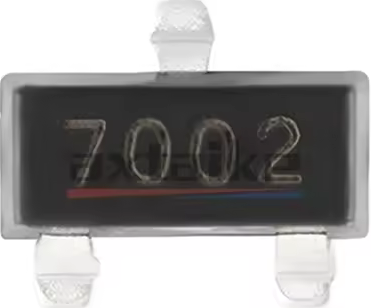
| Package Type | SOT-23 |
Pin Configuration
The 2N7002 is housed in a 3-pin SOT-23 package. The pinout is as follows:
| Pin Number | Pin Name | Description |
|---|---|---|
| 1 | Gate | Controls the MOSFET switching |
| 2 | Source | Connected to the source of current |
| 3 | Drain | Connected to the load or output |
Usage Instructions
How to Use the 2N7002 in a Circuit
Basic Switching Circuit:
- Connect the Drain to the load (e.g., an LED with a current-limiting resistor).
- Connect the Source to ground.
- Apply a control voltage (0V or 5V) to the Gate to switch the load on or off.
Gate Resistor:
- Use a resistor (typically 10kΩ) between the Gate and ground to ensure the MOSFET remains off when no control signal is applied.
Voltage Levels:
- Ensure the Gate-Source voltage (VGS) is within the specified range (e.g., 5V for logic-level operation).
Load Current:
- Verify that the load current does not exceed the maximum continuous Drain current (200mA).
Example: Controlling an LED with Arduino UNO
The 2N7002 can be used to control an LED using an Arduino UNO. Below is an example circuit and code:
Circuit Connections
- Drain: Connect to one terminal of the LED (with a 220Ω resistor in series).
- Source: Connect to ground.
- Gate: Connect to an Arduino digital pin (e.g., pin 9) through a 220Ω resistor.
Arduino Code
// Example code to control an LED using the 2N7002 MOSFET
// Connect the Gate of the 2N7002 to pin 9 of the Arduino

const int mosfetGatePin = 9; // Pin connected to the Gate of the 2N7002

void setup() {
  pinMode(mosfetGatePin, OUTPUT); // Set pin 9 as an output
}

void loop() {
  digitalWrite(mosfetGatePin, HIGH); // Turn the LED on
  delay(1000);                       // Wait for 1 second
  digitalWrite(mosfetGatePin, LOW);  // Turn the LED off
  delay(1000);                       // Wait for 1 second
}
Best Practices
- Avoid exceeding the maximum voltage and current ratings to prevent damage.
- Use a heat sink or proper ventilation if operating near the maximum power dissipation.
- Ensure the Gate-Source voltage is within the recommended range for reliable operation.
Troubleshooting and FAQs
Common Issues and Solutions
| Issue | Possible Cause | Solution |
|---|---|---|
| MOSFET does not switch on | Insufficient Gate-Source voltage | Ensure VGS is at least 5V for logic-level operation. |
| MOSFET overheats | Exceeding maximum current or power dissipation | Reduce load current or improve cooling. |
| Load remains on/off unexpectedly | Floating Gate | Add a pull-down resistor (e.g., 10kΩ) between Gate and Source. |
| Circuit not working as expected | Incorrect pin connections | Double-check the pin configuration and wiring. |
FAQs
Can the 2N7002 be used with 3.3V logic?
Yes, the 2N7002 can operate with 3.3V logic, but ensure the load current and VGS are within the specified range.What is the maximum load current the 2N7002 can handle?
The maximum continuous Drain current is 200mA. For pulsed operation, it can handle up to 800mA.Do I need a heat sink for the 2N7002?
A heat sink is generally not required for low-power applications. However, if operating near the maximum power dissipation (300mW), ensure proper cooling.Can the 2N7002 be used for high-speed switching?
Yes, the 2N7002 is suitable for high-speed switching due to its low gate capacitance and fast response time.