How to Use wind speed: Examples, Pinouts, and Specs
Introduction
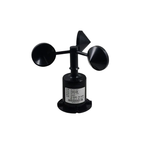
- A wind speed sensor, also known as an anemometer, is a device designed to measure the speed of wind. It is commonly used in meteorology, environmental monitoring, and industrial applications to assess weather conditions, air flow, and ventilation performance.
- Typical use cases include weather stations, renewable energy systems (e.g., wind turbines), HVAC systems, and agricultural monitoring.
Explore Projects Built with wind speed
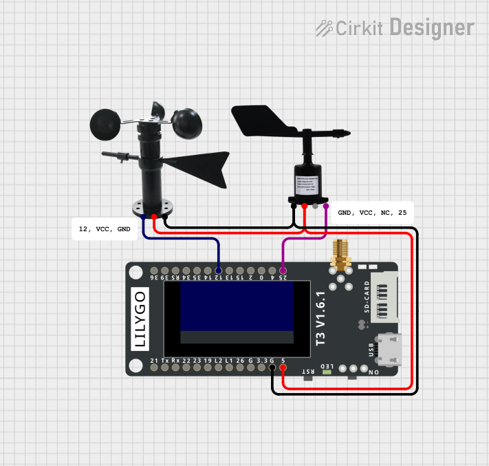
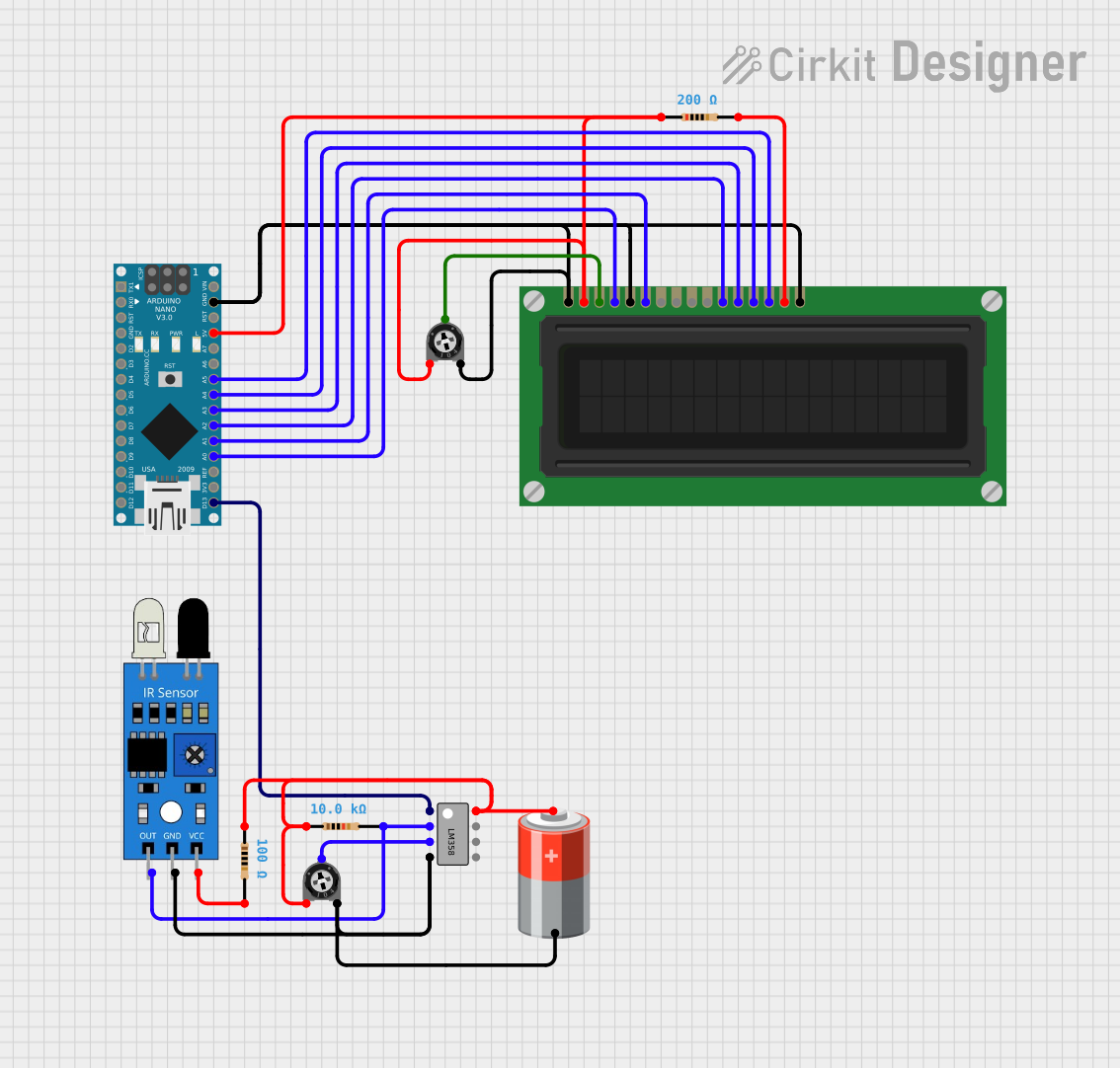
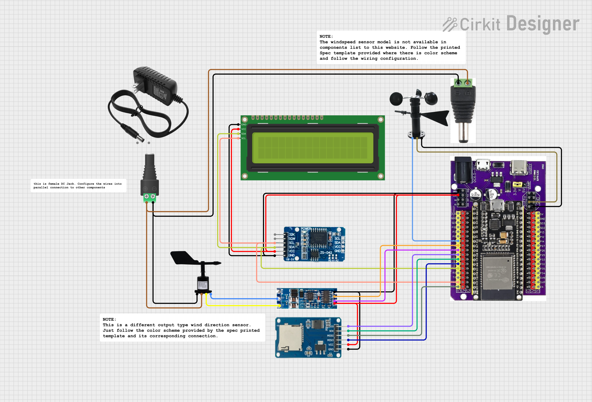
Explore Projects Built with wind speed
Technical Specifications
- Sensor Type: Cup anemometer or ultrasonic (varies by model)
- Operating Voltage: 5V to 24V DC (depending on the model)
- Output Signal: Pulse frequency, analog voltage, or digital communication (e.g., UART)
- Measurement Range: 0.3 m/s to 30 m/s (varies by model)
- Accuracy: ±3% of the measured value
- Operating Temperature: -40°C to 85°C
- Material: Weather-resistant plastic or metal (varies by model)
Pin Configuration and Descriptions
Below is a typical pinout for a wind speed sensor with a pulse output:
| Pin | Name | Description |
|---|---|---|
| 1 | VCC | Power supply input (5V to 24V DC, depending on the sensor model) |
| 2 | GND | Ground connection |
| 3 | Signal (OUT) | Pulse output signal proportional to wind speed |
For sensors with digital communication (e.g., UART), the pinout may include additional pins for TX and RX.
Usage Instructions
Connecting the Sensor:
- Connect the VCC pin to a 5V or 12V power source (check your sensor's datasheet for the exact voltage range).
- Connect the GND pin to the ground of your circuit.
- Connect the Signal (OUT) pin to a microcontroller's digital input pin or an analog input pin, depending on the sensor's output type.
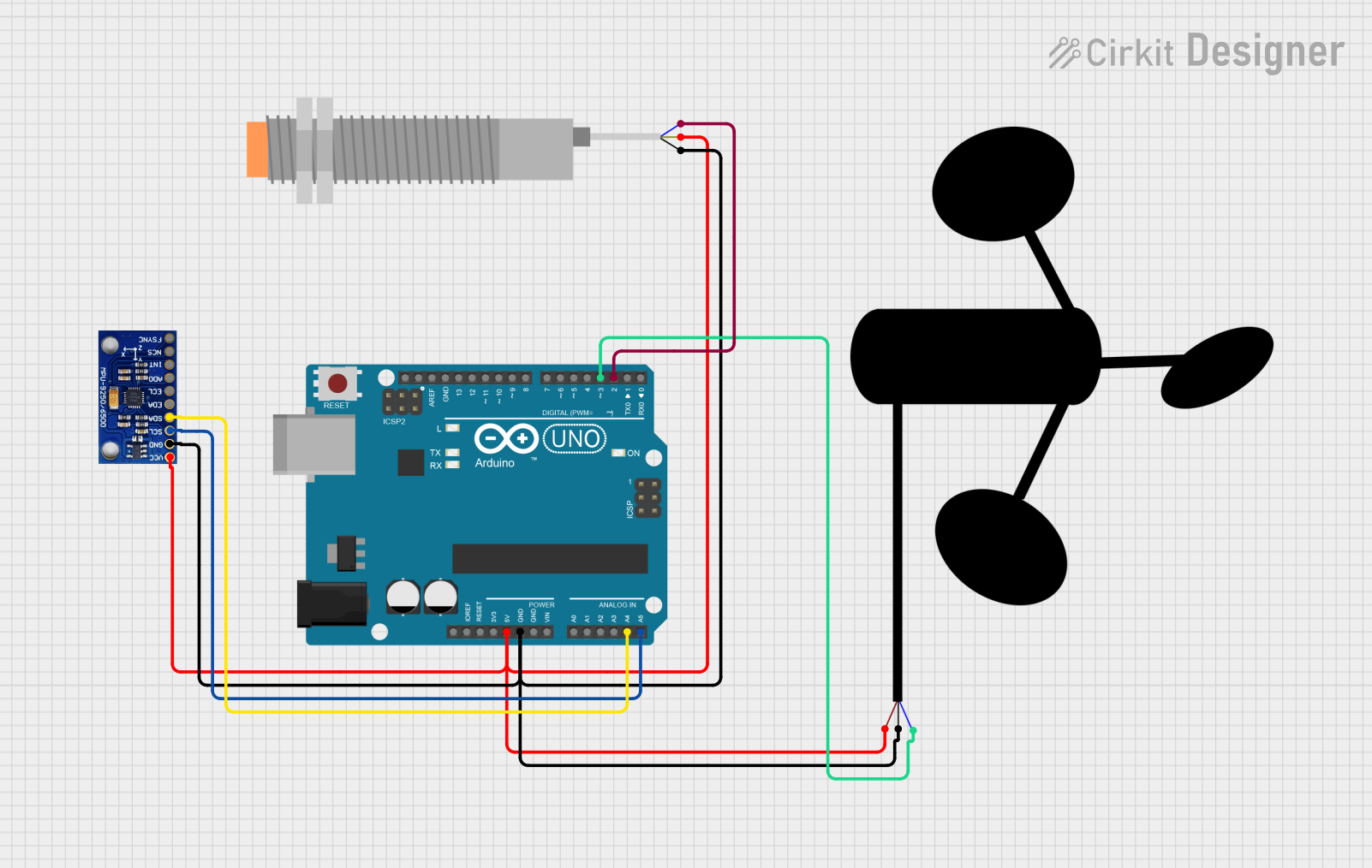
Interfacing with an Arduino UNO:
- If the sensor outputs pulses, you can use an Arduino to count the pulses over a fixed time period to calculate wind speed.
- Below is an example Arduino code to read wind speed from a pulse-based wind speed sensor:
// Wind Speed Sensor Example Code
// This code reads pulses from a wind speed sensor and calculates wind speed.
// Ensure the sensor's signal pin is connected to pin 2 on the Arduino.

const int signalPin = 2;  // Pin connected to the sensor's signal output
volatile int pulseCount = 0;  // Variable to store pulse count
unsigned long lastMillis = 0;  // To track time for calculations
const float calibrationFactor = 2.4;  // Adjust based on your sensor's datasheet

void setup() {
  pinMode(signalPin, INPUT_PULLUP);  // Set signal pin as input with pull-up resistor
  attachInterrupt(digitalPinToInterrupt(signalPin), countPulse, FALLING);
  Serial.begin(9600);  // Initialize serial communication
}

void loop() {
  unsigned long currentMillis = millis();

  // Calculate wind speed every second
  if (currentMillis - lastMillis >= 1000) {
    detachInterrupt(digitalPinToInterrupt(signalPin));  // Disable interrupt temporarily
    float windSpeed = (pulseCount / calibrationFactor);  // Calculate wind speed
    pulseCount = 0;  // Reset pulse count
    lastMillis = currentMillis;  // Update time
    attachInterrupt(digitalPinToInterrupt(signalPin), countPulse, FALLING);  // Re-enable interrupt

    Serial.print("Wind Speed: ");
    Serial.print(windSpeed);
    Serial.println(" m/s");
  }
}

// Interrupt service routine to count pulses
void countPulse() {
  pulseCount++;
}
- Important Considerations:
- Ensure the sensor is mounted securely in an open area, free from obstructions, to get accurate readings.
- For outdoor use, verify that the sensor is weatherproof and resistant to environmental conditions.
- If using a long cable to connect the sensor, consider shielding the cable to reduce noise interference.
Troubleshooting and FAQs
Common Issues
No Output Signal:
- Check the power supply voltage and ensure it matches the sensor's requirements.
- Verify all connections, especially the ground and signal pins.
- Test the sensor with a multimeter to confirm it is functioning.
Inaccurate Readings:
- Ensure the sensor is installed in a location free from obstructions or turbulence.
- Check the calibration factor in your code and adjust it according to the sensor's datasheet.
Intermittent Signal:
- Inspect the wiring for loose connections or damage.
- Use a pull-up resistor on the signal pin if the sensor requires it.
FAQs
Q: Can this sensor measure wind direction?
A: No, this sensor only measures wind speed. For wind direction, you would need a wind vane or a combined anemometer and wind vane sensor.Q: How do I calibrate the sensor?
A: Refer to the sensor's datasheet for the calibration factor. You may need to compare the sensor's output with a known reference to fine-tune the calibration.Q: Can I use this sensor with a Raspberry Pi?
A: Yes, you can connect the sensor to a Raspberry Pi's GPIO pins. Use a library like RPi.GPIO to read pulses or analog signals.
By following this documentation, you should be able to effectively use a wind speed sensor in your projects.