Cirkit Designer Logo
Cirkit Designer
Your all-in-one circuit design IDE
Home / 
Component Documentation

How to Use GY906: Examples, Pinouts, and Specs

Image of GY906
Cirkit Designer LogoDesign with GY906 in Cirkit Designer

Introduction

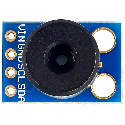
The GY906 is a digital temperature sensor module based on the MLX90614 infrared sensor. It is designed to measure the temperature of objects without requiring direct contact, utilizing infrared radiation. This makes it an excellent choice for non-invasive temperature measurement in a wide range of applications. The GY906 is widely used in medical devices, HVAC systems, robotics, and industrial automation, where accurate and reliable temperature readings are essential.

The module communicates using the I2C protocol, making it easy to integrate with microcontrollers such as the Arduino UNO. Its compact size and high precision make it a versatile and user-friendly component for temperature sensing projects.

Explore Projects Built with GY906

Use Cirkit Designer to design, explore, and prototype these projects online. Some projects support real-time simulation. Click "Open Project" to start designing instantly!
Battery-Powered Emergency Alert System with NUCLEO-F072RB, SIM800L, and GPS NEO 6M
Image of women safety: A project utilizing GY906 in a practical application
This circuit is an emergency alert system that uses a NUCLEO-F072RB microcontroller to send SMS alerts and make calls via a SIM800L GSM module, while obtaining location data from a GPS NEO 6M module. The system is powered by a Li-ion battery and includes a TP4056 module for battery charging and protection, with a rocker switch to control power to the microcontroller.
Cirkit Designer LogoOpen Project in Cirkit Designer
Arduino Nano-Based Wireless Joystick and Motion Controller
Image of hand gesture: A project utilizing GY906 in a practical application
This circuit features an Arduino Nano microcontroller interfaced with an HC-05 Bluetooth module, an MPU-6050 accelerometer/gyroscope, and a KY-023 Dual Axis Joystick Module. The Arduino Nano is powered by a 9V battery through a rocker switch and communicates with the HC-05 for Bluetooth connectivity, reads joystick positions from the KY-023 module via analog inputs, and communicates with the MPU-6050 over I2C to capture motion data. The circuit is likely designed for wireless control and motion sensing applications, such as a remote-controlled robot or a game controller.
Cirkit Designer LogoOpen Project in Cirkit Designer
Arduino Nano Joystick-Controlled Bluetooth Module with Battery Power
Image of padelpro transmitter: A project utilizing GY906 in a practical application
This circuit is a wireless joystick controller that uses an Arduino Nano to read analog signals from a KY-023 Dual Axis Joystick Module and transmits the data via an HC-05 Bluetooth Module. The system is powered by a 18650 Li-Ion battery with a rocker switch for power control.
Cirkit Designer LogoOpen Project in Cirkit Designer
Battery-Powered IoT Tracker with NodeMCU ESP8266, GPS, and GSM
Image of RaahMitra - Smart Helmet: A project utilizing GY906 in a practical application
This circuit is a multi-sensor data acquisition system powered by a Li-ion battery and managed by a NodeMCU ESP8266 microcontroller. It integrates various sensors including a GPS module, an accelerometer, a gyroscope, and a vibration sensor, and communicates data via a SIM800L GSM module. The TP4056 module is used for battery charging and power management.
Cirkit Designer LogoOpen Project in Cirkit Designer

Explore Projects Built with GY906

Use Cirkit Designer to design, explore, and prototype these projects online. Some projects support real-time simulation. Click "Open Project" to start designing instantly!
Image of women safety: A project utilizing GY906 in a practical application
Battery-Powered Emergency Alert System with NUCLEO-F072RB, SIM800L, and GPS NEO 6M
This circuit is an emergency alert system that uses a NUCLEO-F072RB microcontroller to send SMS alerts and make calls via a SIM800L GSM module, while obtaining location data from a GPS NEO 6M module. The system is powered by a Li-ion battery and includes a TP4056 module for battery charging and protection, with a rocker switch to control power to the microcontroller.
Cirkit Designer LogoOpen Project in Cirkit Designer
Image of hand gesture: A project utilizing GY906 in a practical application
Arduino Nano-Based Wireless Joystick and Motion Controller
This circuit features an Arduino Nano microcontroller interfaced with an HC-05 Bluetooth module, an MPU-6050 accelerometer/gyroscope, and a KY-023 Dual Axis Joystick Module. The Arduino Nano is powered by a 9V battery through a rocker switch and communicates with the HC-05 for Bluetooth connectivity, reads joystick positions from the KY-023 module via analog inputs, and communicates with the MPU-6050 over I2C to capture motion data. The circuit is likely designed for wireless control and motion sensing applications, such as a remote-controlled robot or a game controller.
Cirkit Designer LogoOpen Project in Cirkit Designer
Image of padelpro transmitter: A project utilizing GY906 in a practical application
Arduino Nano Joystick-Controlled Bluetooth Module with Battery Power
This circuit is a wireless joystick controller that uses an Arduino Nano to read analog signals from a KY-023 Dual Axis Joystick Module and transmits the data via an HC-05 Bluetooth Module. The system is powered by a 18650 Li-Ion battery with a rocker switch for power control.
Cirkit Designer LogoOpen Project in Cirkit Designer
Image of RaahMitra - Smart Helmet: A project utilizing GY906 in a practical application
Battery-Powered IoT Tracker with NodeMCU ESP8266, GPS, and GSM
This circuit is a multi-sensor data acquisition system powered by a Li-ion battery and managed by a NodeMCU ESP8266 microcontroller. It integrates various sensors including a GPS module, an accelerometer, a gyroscope, and a vibration sensor, and communicates data via a SIM800L GSM module. The TP4056 module is used for battery charging and power management.
Cirkit Designer LogoOpen Project in Cirkit Designer

Technical Specifications

  • Sensor Type: Infrared (IR) temperature sensor
  • Model: MLX90614
  • Operating Voltage: 3.3V to 5V
  • Communication Protocol: I2C
  • Temperature Range:
    • Object Temperature: -70°C to +380°C
    • Ambient Temperature: -40°C to +125°C
  • Accuracy: ±0.5°C (typical, for object temperatures between 0°C and +50°C)
  • Field of View (FOV): 35°
  • Resolution: 0.02°C
  • Current Consumption: 1.5mA (typical)
  • Dimensions: 11mm x 22mm (approx.)

Pin Configuration and Descriptions

The GY906 module has four pins, as described in the table below:

Pin Name Description Notes
VIN Power supply input Connect to 3.3V or 5V
GND Ground Connect to the ground of the circuit
SCL Serial Clock Line (I2C) Connect to the SCL pin of the microcontroller
SDA Serial Data Line (I2C) Connect to the SDA pin of the microcontroller

Usage Instructions

How to Use the GY906 in a Circuit

  1. Power the Module: Connect the VIN pin to a 3.3V or 5V power source and the GND pin to the ground.
  2. Connect I2C Lines: Connect the SCL and SDA pins to the corresponding I2C pins on your microcontroller. For an Arduino UNO:
    • SCL connects to A5.
    • SDA connects to A4.
  3. Install Required Libraries: To use the GY906 with an Arduino, install the Adafruit_MLX90614 library from the Arduino Library Manager.
  4. Write and Upload Code: Use the example code below to read temperature data from the sensor.

Example Code for Arduino UNO

#include <Wire.h>
#include <Adafruit_MLX90614.h>

// Create an instance of the MLX90614 sensor
Adafruit_MLX90614 mlx = Adafruit_MLX90614();

void setup() {
  Serial.begin(9600); // Initialize serial communication at 9600 baud
  Serial.println("GY906 Temperature Sensor Test");

  if (!mlx.begin()) {
    Serial.println("Error: Could not find a valid MLX90614 sensor!");
    while (1); // Halt execution if sensor initialization fails
  }
}

void loop() {
  // Read object and ambient temperatures
  double objectTemp = mlx.readObjectTempC();
  double ambientTemp = mlx.readAmbientTempC();

  // Print the temperatures to the Serial Monitor
  Serial.print("Object Temperature: ");
  Serial.print(objectTemp);
  Serial.println(" °C");

  Serial.print("Ambient Temperature: ");
  Serial.print(ambientTemp);
  Serial.println(" °C");

  delay(1000); // Wait 1 second before the next reading
}

Important Considerations and Best Practices

  • Ensure proper alignment of the sensor with the target object for accurate readings.
  • Avoid placing the sensor in direct sunlight or near heat sources, as this may affect accuracy.
  • Use pull-up resistors (typically 4.7kΩ) on the SDA and SCL lines if they are not already present on the module.
  • Keep the sensor clean and free from dust or debris to maintain optimal performance.

Troubleshooting and FAQs

Common Issues and Solutions

  1. No Data or Incorrect Readings:

    • Ensure the wiring is correct and matches the pin configuration.
    • Verify that the I2C address of the sensor matches the one used in the code (default is 0x5A).
    • Check for loose connections or damaged wires.
  2. Sensor Not Detected:

    • Confirm that the Adafruit_MLX90614 library is installed and included in the code.
    • Ensure the sensor is powered correctly (3.3V or 5V).
    • Use an I2C scanner sketch to verify the sensor's address.
  3. Inaccurate Temperature Readings:

    • Ensure the sensor is not exposed to reflective surfaces or strong IR sources.
    • Allow the sensor to stabilize for a few seconds after powering it on.

FAQs

Q: Can the GY906 measure the temperature of liquids?
A: Yes, the GY906 can measure the temperature of liquids as long as the liquid's surface is visible to the sensor and within its field of view.

Q: What is the maximum distance for accurate temperature measurement?
A: The effective distance depends on the size of the target object and its emissivity. For small objects, the sensor should be placed closer for accurate readings.

Q: Can I use the GY906 with a 3.3V microcontroller?
A: Yes, the GY906 is compatible with both 3.3V and 5V systems.

Q: How do I change the I2C address of the sensor?
A: Changing the I2C address requires reprogramming the sensor's EEPROM. Refer to the MLX90614 datasheet for detailed instructions.