How to Use INA226: Examples, Pinouts, and Specs
Introduction
The INA226 is a high-side current shunt monitor with an integrated I2C interface, designed for precise measurement of voltage, current, and power. It features a built-in 16-bit analog-to-digital converter (ADC) for high-resolution measurements and operates over a wide voltage range, making it suitable for a variety of applications. The INA226 is widely used in power management systems, battery monitoring, server power monitoring, and industrial automation.
Explore Projects Built with INA226


Explore Projects Built with INA226
Common Applications
- Battery management systems
- Power supply monitoring
- Energy metering
- Industrial equipment monitoring
- Server and data center power management
Technical Specifications
Key Technical Details
- Supply Voltage (VCC): 2.7V to 5.5V
- Input Voltage Range (Common-Mode): 0V to 36V
- Shunt Voltage Range: ±81.92mV
- Current Measurement Resolution: 16 bits
- I2C Address Range: Configurable via A0 and A1 pins (up to 16 unique addresses)
- Operating Temperature Range: -40°C to +125°C
- Communication Protocol: I2C (up to 1 MHz)
- Power Consumption: 330 µA (typical)
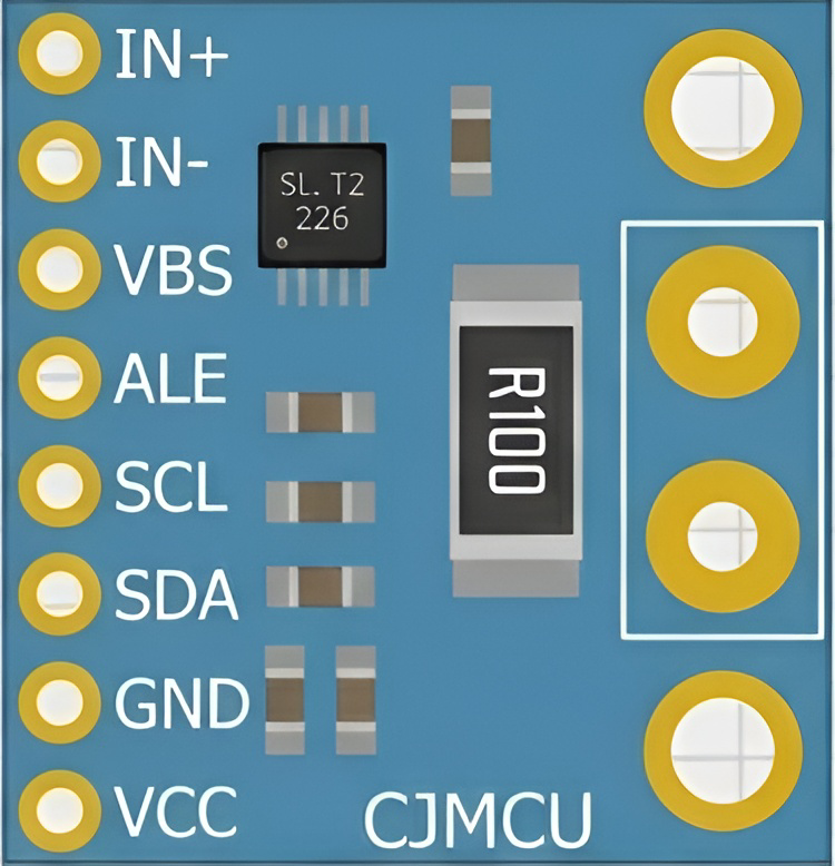
Pin Configuration and Descriptions
The INA226 is available in a 10-pin VSSOP package. Below is the pinout and description:
| Pin | Name | Type | Description |
|---|---|---|---|
| 1 | VIN+ | Input | Positive input for differential voltage measurement across the shunt resistor. |
| 2 | VIN- | Input | Negative input for differential voltage measurement across the shunt resistor. |
| 3 | GND | Power Ground | Ground reference for the device. |
| 4 | SCL | Input | I2C clock line. |
| 5 | SDA | Input/Output | I2C data line. |
| 6 | A0 | Input | Address selection pin 0. |
| 7 | A1 | Input | Address selection pin 1. |
| 8 | ALERT | Output | Alert output for programmable threshold events. |
| 9 | VCC | Power Supply | Power supply input (2.7V to 5.5V). |
| 10 | NC | No Connection | Not internally connected. |
Usage Instructions
How to Use the INA226 in a Circuit
- Power Supply: Connect the VCC pin to a 2.7V to 5.5V power source and the GND pin to ground.
- Shunt Resistor: Place a precision shunt resistor between the load and ground. Connect the VIN+ and VIN- pins across the shunt resistor.
- I2C Communication: Connect the SCL and SDA pins to the corresponding I2C lines of your microcontroller. Use pull-up resistors (typically 4.7kΩ) on both lines.
- Address Configuration: Set the A0 and A1 pins to configure the I2C address. These pins can be tied to VCC, GND, or left floating to select one of 16 possible addresses.
- Alert Pin (Optional): Connect the ALERT pin to a microcontroller GPIO if you want to use the alert functionality for threshold monitoring.
Important Considerations
- Shunt Resistor Selection: Choose a shunt resistor with a low resistance value to minimize power loss, but ensure it provides a measurable voltage drop within the ±81.92mV range.
- I2C Pull-Up Resistors: Ensure proper pull-up resistors are used on the I2C lines to maintain signal integrity.
- Bypass Capacitor: Place a 0.1µF ceramic capacitor close to the VCC pin for power supply decoupling.
- Alert Configuration: Use the INA226's internal registers to configure the ALERT pin for overcurrent, undervoltage, or other threshold events.
Example Code for Arduino UNO
Below is an example of how to interface the INA226 with an Arduino UNO to measure current and voltage:
#include <Wire.h>

// INA226 I2C address (default: 0x40)
#define INA226_ADDRESS 0x40

// INA226 register addresses
#define REG_CONFIG 0x00
#define REG_SHUNT_VOLTAGE 0x01
#define REG_BUS_VOLTAGE 0x02

void setup() {
  Wire.begin(); // Initialize I2C communication
  Serial.begin(9600); // Initialize serial communication for debugging

  // Configure the INA226
  Wire.beginTransmission(INA226_ADDRESS);
  Wire.write(REG_CONFIG); // Point to the configuration register
  Wire.write(0x45); // MSB: Set averaging and conversion times
  Wire.write(0x27); // LSB: Enable shunt and bus voltage measurements
  Wire.endTransmission();
}

void loop() {
  float shuntVoltage = readShuntVoltage();
  float busVoltage = readBusVoltage();
  float current = shuntVoltage / 0.1; // Assuming a 0.1Ω shunt resistor

  Serial.print("Bus Voltage: ");
  Serial.print(busVoltage);
  Serial.println(" V");

  Serial.print("Shunt Voltage: ");
  Serial.print(shuntVoltage);
  Serial.println(" mV");

  Serial.print("Current: ");
  Serial.print(current);
  Serial.println(" A");

  delay(1000); // Wait 1 second before the next reading
}

float readShuntVoltage() {
  int16_t rawValue = readRegister(REG_SHUNT_VOLTAGE);
  return rawValue * 0.0025; // Convert to mV (LSB = 2.5µV)
}

float readBusVoltage() {
  int16_t rawValue = readRegister(REG_BUS_VOLTAGE);
  return rawValue * 0.00125; // Convert to V (LSB = 1.25mV)
}

int16_t readRegister(uint8_t reg) {
  Wire.beginTransmission(INA226_ADDRESS);
  Wire.write(reg); // Point to the desired register
  Wire.endTransmission();

  Wire.requestFrom(INA226_ADDRESS, 2); // Request 2 bytes
  int16_t value = (Wire.read() << 8) | Wire.read(); // Combine MSB and LSB
  return value;
}
Troubleshooting and FAQs
Common Issues
No I2C Communication:
- Ensure the INA226 is powered correctly (VCC and GND connected).
- Verify the I2C address matches the configuration of the A0 and A1 pins.
- Check for proper pull-up resistors on the SDA and SCL lines.
Incorrect Current or Voltage Readings:
- Verify the shunt resistor value and ensure it is within the measurable range.
- Check for loose or incorrect connections across the shunt resistor.
- Ensure the INA226 configuration register is set correctly.
Alert Pin Not Functioning:
- Confirm the ALERT pin is connected to the microcontroller.
- Verify the alert thresholds are configured in the INA226 registers.
Tips for Troubleshooting
- Use an I2C scanner sketch to confirm the INA226 is detected on the I2C bus.
- Double-check all connections, especially the shunt resistor and I2C lines.
- Use an oscilloscope or logic analyzer to debug I2C communication if necessary.
FAQs
Q: Can the INA226 measure negative currents?
A: Yes, the INA226 can measure bidirectional currents if configured appropriately. Ensure the shunt voltage range is within ±81.92mV.
Q: What is the maximum sampling rate of the INA226?
A: The sampling rate depends on the averaging and conversion time settings. The fastest conversion time is 140µs per measurement.
Q: Can I use the INA226 with a 3.3V microcontroller?
A: Yes, the INA226 is compatible with 3.3V systems as long as the VCC voltage is within the 2.7V to 5.5V range.