How to Use SOP8: Examples, Pinouts, and Specs
Introduction
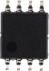
The SOP8 (Small Outline Package 8) is a surface-mount integrated circuit (IC) package with eight pins. It is widely used in modern electronics due to its compact size, lightweight design, and efficient thermal performance. SOP8 packages are commonly found in applications such as memory chips, operational amplifiers, voltage regulators, and microcontrollers. Their small form factor makes them ideal for high-density circuit boards in consumer electronics, automotive systems, and industrial devices.
Explore Projects Built with SOP8
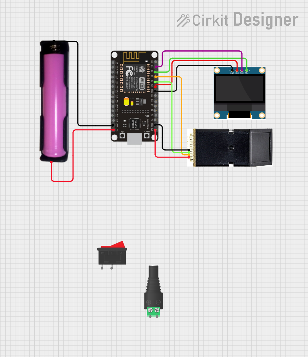

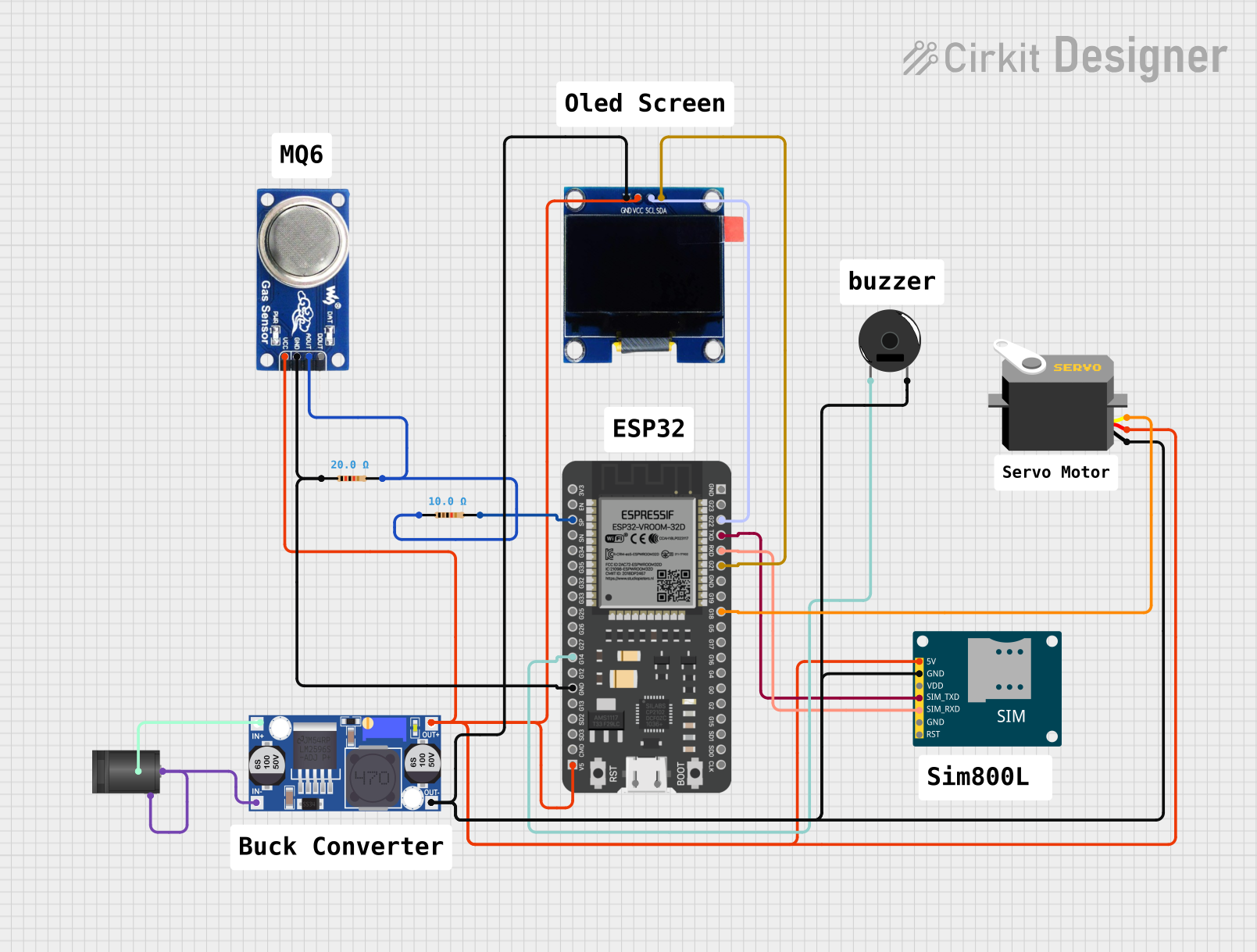

Explore Projects Built with SOP8
Technical Specifications
The SOP8 package is designed to meet the needs of compact and efficient circuit designs. Below are the key technical details and pin configuration:
Key Technical Details
| Parameter | Specification |
|---|---|
| Package Type | SOP8 (Small Outline Package, 8 pins) |
| Pin Count | 8 |
| Body Width | 3.9 mm |
| Body Length | 4.9 mm |
| Lead Pitch | 1.27 mm |
| Maximum Height | 1.75 mm |
| Thermal Resistance (θJA) | Typically 100-150 °C/W |
| Mounting Type | Surface Mount Technology (SMT) |
Pin Configuration and Descriptions
The pin configuration of an SOP8 package varies depending on the specific IC housed within the package. Below is a general example of an SOP8 pinout for a typical operational amplifier (Op-Amp):
| Pin Number | Pin Name | Description |
|---|---|---|
| 1 | V+ | Positive power supply |
| 2 | Inverting Input | Inverting input terminal (-) |
| 3 | Non-Inverting Input | Non-inverting input terminal (+) |
| 4 | GND | Ground (negative power supply) |
| 5 | Output | Output terminal |
| 6 | NC (No Connect) | Not connected (varies by IC) |
| 7 | NC (No Connect) | Not connected (varies by IC) |
| 8 | V- | Negative power supply (if applicable) |
Note: The pinout may differ depending on the specific IC inside the SOP8 package. Always refer to the datasheet of the specific component for accurate pin descriptions.
Usage Instructions
The SOP8 package is designed for surface-mount technology (SMT) and is soldered directly onto a printed circuit board (PCB). Below are the steps and best practices for using an SOP8 component:
How to Use the SOP8 in a Circuit
- Identify the Pinout: Refer to the datasheet of the specific IC housed in the SOP8 package to understand the pin configuration.
- Prepare the PCB: Ensure the PCB has the correct footprint for the SOP8 package. The pad layout should match the pin pitch (1.27 mm) and dimensions of the package.
- Soldering: Use a reflow soldering process or a soldering iron with a fine tip to attach the SOP8 component to the PCB. Apply solder paste to the pads before placing the component.
- Power Supply: Connect the power supply pins (e.g., V+ and GND) to the appropriate voltage levels as specified in the datasheet.
- Signal Connections: Connect the input and output pins to the corresponding circuit elements.
Important Considerations and Best Practices
- Thermal Management: Ensure proper thermal dissipation by designing the PCB with thermal vias or copper planes if the IC generates significant heat.
- Avoid Overheating: During soldering, avoid excessive heat that could damage the component. Use a temperature-controlled soldering iron or reflow oven.
- Verify Connections: Double-check all connections to ensure the correct pinout is followed. Incorrect connections can damage the IC or the circuit.
- Static Protection: Handle the SOP8 component with anti-static precautions to prevent electrostatic discharge (ESD) damage.
Example: Using an SOP8 EEPROM with Arduino UNO
Below is an example of connecting an SOP8 EEPROM (e.g., 24LC256) to an Arduino UNO:
Circuit Connections
| SOP8 Pin | Function | Arduino Pin |
|---|---|---|
| 1 | A0 (Address Pin) | GND |
| 2 | A1 (Address Pin) | GND |
| 3 | A2 (Address Pin) | GND |
| 4 | GND | GND |
| 5 | SDA (Data Line) | A4 |
| 6 | SCL (Clock Line) | A5 |
| 7 | WP (Write Protect) | GND |
| 8 | VCC (Power) | 5V |
Arduino Code Example
#include <Wire.h> // Include the Wire library for I2C communication

#define EEPROM_I2C_ADDRESS 0x50 // I2C address of the EEPROM

void setup() {
  Wire.begin(); // Initialize I2C communication
  Serial.begin(9600); // Start serial communication for debugging
  Serial.println("EEPROM Test Start");

  // Write a byte to EEPROM
  Wire.beginTransmission(EEPROM_I2C_ADDRESS);
  Wire.write(0x00); // Set memory address to 0x00
  Wire.write(0x42); // Write the value 0x42
  Wire.endTransmission();
  delay(10); // Wait for the write cycle to complete

  // Read the byte back from EEPROM
  Wire.beginTransmission(EEPROM_I2C_ADDRESS);
  Wire.write(0x00); // Set memory address to 0x00
  Wire.endTransmission();

  Wire.requestFrom(EEPROM_I2C_ADDRESS, 1); // Request 1 byte from EEPROM
  if (Wire.available()) {
    byte data = Wire.read(); // Read the byte
    Serial.print("Read Data: 0x");
    Serial.println(data, HEX); // Print the data in hexadecimal format
  }
}

void loop() {
  // No repeated actions in this example
}
Troubleshooting and FAQs
Common Issues and Solutions
Component Not Detected:
- Cause: Incorrect pin connections or soldering issues.
- Solution: Verify the pinout and ensure all connections are secure. Check for solder bridges or cold joints.
Overheating During Soldering:
- Cause: Excessive heat applied during soldering.
- Solution: Use a temperature-controlled soldering iron and limit the soldering time to a few seconds per pin.
Incorrect Data Read/Write:
- Cause: Mismatched I2C address or incorrect wiring.
- Solution: Double-check the I2C address and ensure SDA/SCL lines are properly connected.
Static Damage:
- Cause: Handling the component without ESD precautions.
- Solution: Use an anti-static wrist strap and work on an ESD-safe surface.
FAQs
Q: Can I use SOP8 components on a breadboard?
A: SOP8 components are designed for surface-mount applications and cannot be directly used on a breadboard. However, you can use an SOP8-to-DIP adapter to make them breadboard-compatible.
Q: How do I identify pin 1 on an SOP8 package?
A: Pin 1 is typically marked with a dot or a chamfered edge on the package. Refer to the datasheet for specific markings.
Q: What is the maximum current an SOP8 package can handle?
A: The maximum current depends on the specific IC housed in the SOP8 package. Refer to the datasheet for the current rating of the component.