How to Use RIoTboard: Examples, Pinouts, and Specs
Introduction
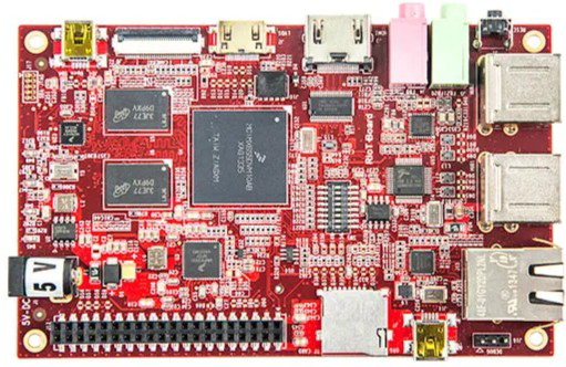
The RIoTboard is a high-performance development platform tailored for Internet of Things (IoT) applications. It is equipped with a powerful Freescale i.MX 6Solo processor, a variety of connectivity options, and support for multiple sensors and peripherals. This makes it an excellent choice for prototyping and developing IoT solutions. The RIoTboard is designed to provide developers with a robust and flexible platform for creating smart devices and connected systems.
Explore Projects Built with RIoTboard


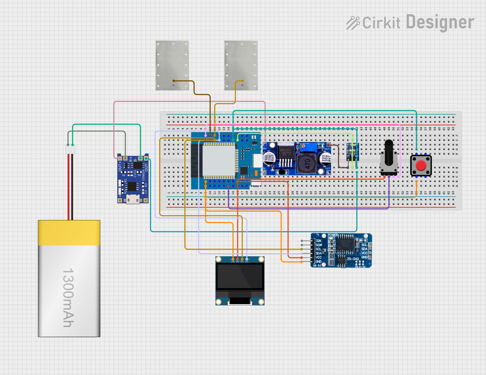
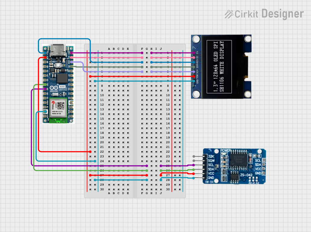
Explore Projects Built with RIoTboard
Common Applications and Use Cases
- Smart home automation systems
- Industrial IoT monitoring and control
- Wearable technology prototyping
- Environmental monitoring with sensors
- Educational projects and IoT learning platforms
Technical Specifications
Key Technical Details
| Specification | Details |
|---|---|
| Processor | Freescale i.MX 6Solo ARM Cortex-A9 (1 GHz) |
| Memory | 1 GB DDR3 RAM |
| Storage | 4 GB eMMC, microSD card slot (up to 32 GB) |
| Connectivity | Ethernet, Wi-Fi (via external module), USB |
| Display Support | HDMI, LVDS, and LCD interface |
| Operating System Support | Android, Linux |
| GPIO Pins | 66 GPIO pins |
| Power Supply | 5V DC (via barrel jack or USB) |
| Dimensions | 120 mm x 75 mm |
Pin Configuration and Descriptions
The RIoTboard features a 66-pin GPIO header, which includes various interfaces such as UART, SPI, I2C, and PWM. Below is a summary of the key pin functions:
| Pin Number | Function | Description |
|---|---|---|
| 1-4 | GND | Ground pins |
| 5-6 | 5V | 5V power supply pins |
| 7-8 | 3.3V | 3.3V power supply pins |
| 9-12 | UART1_TX/RX | UART1 transmit and receive pins |
| 13-16 | I2C1_SCL/SDA | I2C1 clock and data pins |
| 17-20 | SPI1_MOSI/MISO | SPI1 data in/out pins |
| 21-24 | PWM1/PWM2 | PWM output pins |
| 25-66 | GPIO | General-purpose input/output pins |
Usage Instructions
How to Use the RIoTboard in a Circuit
- Powering the Board: Connect a 5V DC power supply to the barrel jack or use a USB cable to power the board.
- Connecting Peripherals: Attach sensors, actuators, or other peripherals to the GPIO pins. Ensure proper pin mapping and voltage levels.
- Programming the Board: Use a USB connection to upload code or interact with the board. The RIoTboard supports Android and Linux, so you can use tools like the Android SDK or Linux-based development environments.
- Networking: For IoT applications, connect the board to a network using Ethernet or an external Wi-Fi module.
Important Considerations and Best Practices
- Voltage Levels: Ensure that all connected peripherals operate at 3.3V or use level shifters for compatibility.
- Heat Management: The processor may generate heat during intensive tasks. Consider using a heatsink for better thermal management.
- Static Protection: Handle the board with care to avoid damage from electrostatic discharge (ESD).
- Software Compatibility: Verify that your chosen operating system and software tools are compatible with the RIoTboard.
Example: Connecting the RIoTboard to an Arduino UNO
The RIoTboard can communicate with an Arduino UNO via UART. Below is an example of Arduino code to send data to the RIoTboard:
// Arduino code to send data to the RIoTboard via UART
void setup() {
  Serial.begin(9600); // Initialize UART communication at 9600 baud
}

void loop() {
  Serial.println("Hello, RIoTboard!"); // Send a message to the RIoTboard
  delay(1000); // Wait for 1 second before sending the next message
}
On the RIoTboard, you can use a terminal application (e.g., Minicom or PuTTY) to receive and display the data sent from the Arduino.
Troubleshooting and FAQs
Common Issues and Solutions
The board does not power on:
- Ensure the power supply is providing 5V DC and is properly connected.
- Check for loose connections or damaged cables.
Peripherals are not working:
- Verify that the peripherals are connected to the correct GPIO pins.
- Check the voltage levels and ensure compatibility with the RIoTboard.
No output on the display:
- Ensure the HDMI or LCD cable is securely connected.
- Verify that the display is powered on and set to the correct input source.
Unable to connect to the network:
- For Ethernet, check the cable connection and network settings.
- For Wi-Fi, ensure the external module is properly configured and within range.
FAQs
Q: Can I use the RIoTboard with a battery?
A: Yes, you can use a 5V battery pack with a barrel jack connector to power the board.Q: What operating systems are supported?
A: The RIoTboard supports Android and Linux distributions such as Yocto and Ubuntu.Q: How do I update the firmware?
A: Firmware updates can be performed via USB or SD card. Refer to the official documentation for detailed instructions.Q: Can I use the RIoTboard for machine learning applications?
A: Yes, the RIoTboard's powerful processor and Linux support make it suitable for lightweight machine learning tasks.
This documentation provides a comprehensive guide to using the RIoTboard for IoT development. For further assistance, consult the official RIoTboard resources or community forums.