How to Use tja1051: Examples, Pinouts, and Specs
Introduction
The TJA1051 is a high-speed CAN (Controller Area Network) transceiver designed for automotive and industrial applications. It acts as a reliable interface between the CAN protocol controller and the physical CAN bus, enabling robust communication in distributed systems. The TJA1051 supports data rates of up to 1 Mbps and features low power consumption, making it ideal for modern vehicle communication systems, including body control modules, powertrain systems, and infotainment.
Explore Projects Built with tja1051


Explore Projects Built with tja1051
Common Applications:
- Automotive communication systems (e.g., body control, engine management)
- Industrial automation and control networks
- Electric vehicle (EV) battery management systems
- Robotics and distributed embedded systems
Technical Specifications
Key Technical Details:
| Parameter | Value |
|---|---|
| Supply Voltage (Vcc) | 4.5 V to 5.5 V |
| Data Rate | Up to 1 Mbps |
| Bus Voltage Range | -27 V to +40 V |
| Standby Current | < 10 µA (in standby mode) |
| Operating Temperature | -40°C to +125°C |
| ESD Protection | ±8 kV (HBM) on bus pins |
| Transceiver Modes | Normal, Standby, and Silent modes |
Pin Configuration and Descriptions:
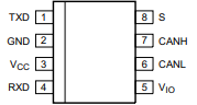
The TJA1051 is typically available in an 8-pin SO8 package. Below is the pinout and description:
| Pin No. | Pin Name | Description |
|---|---|---|
| 1 | TXD | Transmit Data Input: Connects to the CAN controller's transmit output. |
| 2 | GND | Ground: Connect to the system ground. |
| 3 | VCC | Supply Voltage: Connect to a 5 V power supply. |
| 4 | RXD | Receive Data Output: Outputs data received from the CAN bus. |
| 5 | VIO | I/O Voltage Supply: Allows interfacing with controllers operating at lower voltages. |
| 6 | CANL | CAN Low: Connect to the CAN bus low line. |
| 7 | CANH | CAN High: Connect to the CAN bus high line. |
| 8 | STB | Standby Control: Controls the operating mode (Normal/Standby/Silent). |
Usage Instructions
How to Use the TJA1051 in a Circuit:
- Power Supply: Connect the VCC pin to a regulated 5 V power supply and the GND pin to the system ground.
- CAN Bus Connection: Connect the CANH and CANL pins to the respective high and low lines of the CAN bus. Use a 120-ohm termination resistor across CANH and CANL at each end of the bus.
- Controller Interface:
- Connect the TXD pin to the CAN controller's transmit output.
- Connect the RXD pin to the CAN controller's receive input.
- If the controller operates at a lower voltage (e.g., 3.3 V), connect the VIO pin to the controller's supply voltage.
- Mode Selection: Use the STB pin to control the operating mode:
- Pull STB low for Normal mode.
- Pull STB high for Standby mode.
- Leave STB floating for Silent mode.
Important Considerations:
- Ensure proper decoupling by placing a 100 nF capacitor close to the VCC pin.
- Avoid exceeding the maximum voltage ratings on any pin to prevent damage.
- Use proper PCB layout techniques to minimize noise and ensure reliable communication.
Example Code for Arduino UNO:
Below is an example of how to interface the TJA1051 with an Arduino UNO using an MCP2515 CAN controller module:
#include <SPI.h>
#include <mcp_can.h>

// Define the SPI CS pin for the MCP2515 module
#define CAN_CS_PIN 10

// Initialize the MCP2515 CAN controller
MCP_CAN CAN(CAN_CS_PIN);

void setup() {
  Serial.begin(115200);  // Initialize serial communication for debugging

  // Initialize the CAN bus at 500 kbps
  if (CAN.begin(MCP_ANY, CAN_500KBPS, MCP_8MHZ) == CAN_OK) {
    Serial.println("CAN bus initialized successfully!");
  } else {
    Serial.println("CAN bus initialization failed!");
    while (1);  // Halt execution if initialization fails
  }

  CAN.setMode(MCP_NORMAL);  // Set CAN controller to Normal mode
  Serial.println("CAN controller set to Normal mode.");
}

void loop() {
  // Example: Send a CAN message with ID 0x100 and 8 bytes of data
  byte data[8] = {0x01, 0x02, 0x03, 0x04, 0x05, 0x06, 0x07, 0x08};
  if (CAN.sendMsgBuf(0x100, 0, 8, data) == CAN_OK) {
    Serial.println("Message sent successfully!");
  } else {
    Serial.println("Error sending message.");
  }

  delay(1000);  // Wait 1 second before sending the next message
}
Troubleshooting and FAQs
Common Issues:
No Communication on the CAN Bus:
- Ensure the CANH and CANL lines are properly connected and terminated with 120-ohm resistors.
- Verify that the TJA1051 is powered correctly and the STB pin is set to the desired mode.
High Error Rates:
- Check for proper grounding and minimize noise in the circuit.
- Ensure the data rate matches the configuration of all devices on the CAN bus.
Device Not Responding:
- Verify the connections between the TJA1051 and the CAN controller.
- Ensure the VIO pin is connected to the correct voltage if the controller operates at a lower voltage.
FAQs:
Q: Can the TJA1051 operate at 3.3 V?
A: The TJA1051 requires a 5 V supply for VCC, but the VIO pin allows interfacing with 3.3 V logic controllers.
Q: What is the purpose of the Silent mode?
A: Silent mode disables the transmitter while keeping the receiver active, allowing the device to monitor the CAN bus without affecting communication.
Q: How do I protect the TJA1051 from voltage spikes?
A: Use TVS (Transient Voltage Suppressor) diodes on the CANH and CANL lines to protect against voltage transients.
By following this documentation, users can effectively integrate the TJA1051 into their CAN-based systems for reliable communication.